


60
OPM-4240 / OPM-4240R
61
Infinitely Expandable
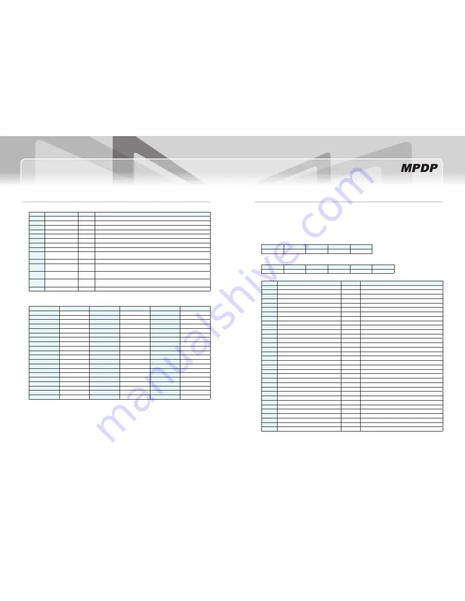
Data: ID(1 byte) + Status(30 byte)
-
no.
Data
Length
Explanation
0
ID
1 byte
Range: 1 ~ 225(for Full MPDP: 15 x 15)
1
Input Source
1 byte
0x0C: PC, 0x0E: DVI, 0x0D: DTV, 0x07: DVD, 0x05: S-Video, 0x02: Video
2
Resolution
1 byte
Value for the detected Resolution
3
PWR Status
1 byte
0: Power Off, 1: Power On
4
BIC Mode
1 byte
0: BIC Off, 1: BIC On
5
Global Offset
1 byte
0: Global Offset Off, 1: Global Offset On
6
Color Temp.
1 byte
0: Normal mode, 1: Studio mode
7
Auto-Power Mode
1 byte
0: Auto-Power Off, 1: Auto-Power On
8~13
F/W Version
6 byte
Year: 2 byte, Month: 2byte, Day: 2byte
2012
Year
12
Month
29
Day →
0x01 0x02 0x01 0x02 0x02 0x09
14
Video Zoom Level
1 byte
Default: 5, Allowable range: 1 ~ 9
15~22
S/N
8 byte
123456
→
0x00 0x00 0x01 0x02 0x03 0x04 0x05 0x06
1
→
0x00 0x00 0x00 0x00 0x00 0x00 0x00 0x01
23~28
Elapsed Time
6 byte
54321
→
0x00 0x05 0x04 0x03 0x02 0x01
10
→
0x00 0x00 0x00 0x00 0x01 0x00
29
Temperature
1 byte
0(0x00): 0
℃
~ 127(0x7F): 127
℃
/ 128(0x80): -1
℃
~ 254(0xFE): -127
℃
0xFF: Temp. Sensor Error
30
FAN Status
1 byte
0x30: Good, 0x31: Error
Check Sum
-
:Add all the values in "Data" area. Then perform "NOT" operation.
< Detected Resolution (Different from supporting Resolution)>
Resolution
Value
Resolution
Value
Resolution
Value
640x480x60
0(0x00)
720Px60
20(0x14)
1600x1200x50
43(0x2B)
640x480x85
1(0x01)
720Px50
21(0x15)
800x600x50
44(0x2C)
800x600x56
2(0x02)
576Px50
22(0x16)
1360x768x60
45(0x2D)
800x600x60
3(0x03)
480Px60
23(0x17)
640x350x85
46(0x2E)
800x600x75
4(0x04)
1920x1080ix60
24(0x18)
640x480x75
47(0x2F)
800x600x85
5(0x05)
1920x1080ix50
25(0x19)
640x480x72
48(0x30)
853x480x60
6(0x06)
1280x720Px60
26(0x1A)
1152x864x75
49(0x31)
1024x768x60
7(0x07)
1280x720Px50
27(0x1B)
1280x720x60
50(0x32)
1024x768x70
8(0x08)
PAL
28(0x1C)
1280x768x75
51(0x33)
1024x768x75
9(0x09)
SECAM
29(0x1D)
1280x1024x75
52(0x34)
1024x768x85
10(0x0A)
PALP
30(0x1E)
1366x768x50
53(0x35)
1280x768x60
11(0x0B)
NTSC
31(0x1F)
1400x1050x50
54(0x36)
1280x960x60
12(0x0C)
NTSCP
32(0x20)
1440x900x60
55(0x37)
1280x1024x60
13(0x0D)
Unknown
34(0x22)
576ix50
56(0x38)
1366x768x60
14(0x0E)
No-Signal
35(0x23)
480ix60
57(0x39)
1600x1200x60
15(0x0F)
853x480x50
38(0x26)
1080px60
58(0x3A)
1400x1050x60
16(0x10)
1280x1024x50
39(0x27)
1080px50
59(0x3B)
1706x960x60
17(0x11)
1360x768x50
40(0x28)
1920x1080px60
60(0x3C)
1080ix60
18(0x12)
1600x900x50
41(0x29)
1920x1080px50
61(0x3D)
1080ix50
19(0x13)
1600x900x60
42(0x2A)
Theresolutionsinredanditaliccanbedetected,buttheyarenotsupportingresolution.
※
Get Picture Control Data
3.24.
Command for finding out the value for current Picture Control Data such as User mode, White Balance, Graphic, and Video.
-
Command Code: 0x88
-
Protocol Format - Two way communication (Send to PDP, Receive from PDP)
-
Caution 1: It will not respond during Stand-by. It should be executed only during operating status.
Caution 2: Values by Color temperature (Normal mode/ Studio mode) will be displayed.
* Send to PDP
STX
CMD
Length
ID
ETX
1 byte
1 byte
1 byte
1 byte
1 byte
Data: ID(1 byte)
-
* Receive From PDP
STX
CMD
Length
Data
Check Sum
ETX
1 byte
1 byte
1 byte
51 byte
1 byte
1 byte
Data: ID(1 byte) + Status(30 byte)
-
no.
Data
Length
Explanation
0
ID
1 byte
Range: 1 ~ 225(for Full MPDP: 15 x 15)
1
User Mode – Brightness
1 byte
Range: 0(0x00) ~ 100(0x64)
2
User Mode – Contrast
1 byte
Range: 0(0x00) ~ 100(0x64)
3
User Mode – Sharpness
1 byte
Range: 0(0x00) ~ 28(0x1C)
4
User Mode – Color
1 byte
Range: 0(0x00) ~ 100(0x64)
5
User Mode – Tint
1 byte
Range: 0(0x00) ~ 90(0x5A)
6
White Balance – Gain R
1 byte
Range: 0(0x00) ~ 255(0xFF)
7
White Balance – Gain G
1 byte
Range: 0(0x00) ~ 255(0xFF)
8
White Balance – Gain B
1 byte
Range: 0(0x00) ~ 255(0xFF)
9
White Balance – Offset R
1 byte
Range: 0(0x00) ~ 255(0xFF)
10
White Balance – Offset G
1 byte
Range: 0(0x00) ~ 255(0xFF)
11
White Balance – Offset B
1 byte
Range: 0(0x00) ~ 255(0xFF)
12~13
Graphic(PC) – Gain R
2 byte
Range: 0(0x00) ~ 1023(0x3FF)
14~15
Graphic(PC) – Gain G
2 byte
Range: 0(0x00) ~ 1023(0x3FF)
16~17
Graphic(PC) – Gain B
2 byte
Range: 0(0x00) ~ 1023(0x3FF)
18~19
Graphic(PC) – Offset R
2 byte
Range: 0(0x00) ~ 1023(0x3FF)
20~21
Graphic(PC) – Offset G
2 byte
Range: 0(0x00) ~ 1023(0x3FF)
22~23
Graphic(PC) – Offset B
2 byte
Range: 0(0x00) ~ 1023(0x3FF)
24~25
Graphic(DTV) – Gain R
2 byte
Range: 0(0x00) ~ 1023(0x3FF)
26~27
Graphic(DTV) – Gain G
2 byte
Range: 0(0x00) ~ 1023(0x3FF)
28~29
Graphic(DTV) – Gain B
2 byte
Range: 0(0x00) ~ 1023(0x3FF)
30~31
Graphic(DTV) – Offset R
2 byte
Range: 0(0x00) ~ 1023(0x3FF)
32~33
Graphic(DTV) – Offset G
2 byte
Range: 0(0x00) ~ 1023(0x3FF)
34~35
Graphic(DTV) – Offset B
2 byte
Range: 0(0x00) ~ 1023(0x3FF)
36~37
Graphic(DVD) – Gain R
2 byte
Range: 0(0x00) ~ 1023(0x3FF)
38~39
Graphic(DVD) – Gain G
2 byte
Range: 0(0x00) ~ 1023(0x3FF)
40~41
Graphic(DVD) – Gain B
2 byte
Range: 0(0x00) ~ 1023(0x3FF)
42~43
Graphic(DVD) – Offset R
2 byte
Range: 0(0x00) ~ 1023(0x3FF)
44~45
Graphic(DVD) – Offset G
2 byte
Range: 0(0x00) ~ 1023(0x3FF)
46~47
Graphic(DVD) – Offset B
2 byte
Range: 0(0x00) ~ 1023(0x3FF)
48
Video – Brightness
1 byte
Range: 0(0x00) ~ 255(0xFF)
49
Video – Contrast
1 byte
Range: 0(0x00) ~ 255(0xFF)
50
Video - Color
1 byte
Range: 0(0x00) ~ 255(0xFF)
Check Sum
-
: Add all the values in "Data" area. Then perform "NOT" operation.


