background image

- 96 -

- 97 -

ST

AND UNIT

W

ALL UNIT

GRAPHIC C

ONFIG'

FRAME INS

TALL'

SENSOR C

ONFIG'

OPERA

TION

SCREEN C

ONFIG'

4

.

2

. Start MSCS


y

MSCS is an application program needed to control MPDP.


y

When you execute MSCS for your product at the installation screen, it will create a new folder at C:/Program 
File/MSCS  and an icon on your computer screen. 


y

By double clicking the MSCS icon, the initial screen image of MSCS will be displayed as shown in the picture.  

<MSCS Window (Multi Screen Control system)>

4

.

3

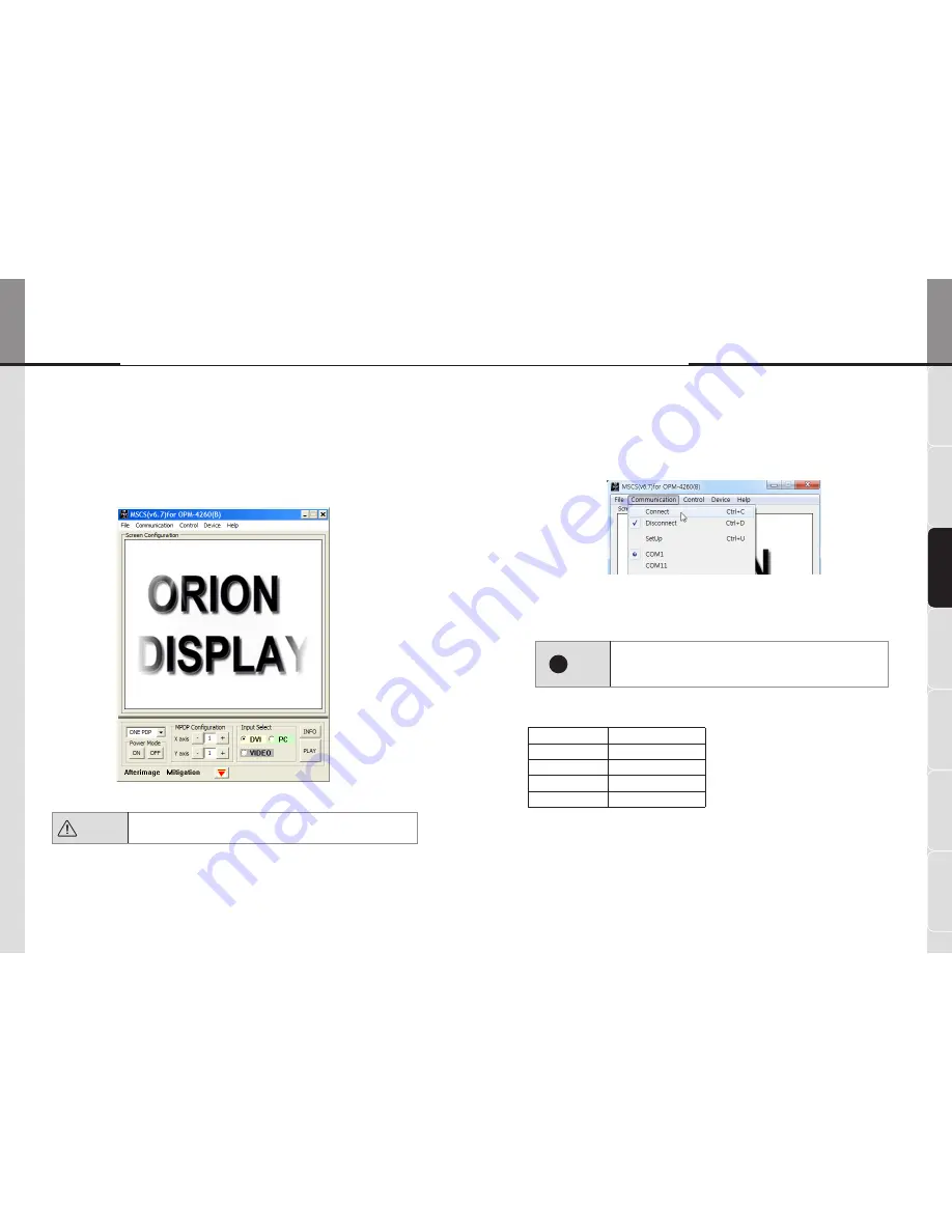
. Setting of COM Port


y

Com Port connects or disconnects the communication between PC and MPDP.


y

Connect MPDP to PC Com Port via RS-

232

C cable.


y

Go to MSCS Menu -> Communication and set Com Port. Click 'Connect' using mouse or press 'Ctrl+C' using 
keyboard.


y

 In order to disconnect communication, click 'Disconnect' using mouse or press 'Ctrl+D' using keyboard. 

!


Note

•  When you use USB-to-RS-

232

C converters, you need to set Com Port 

again, because MSCS uses one of Com Port no. 

1

 to 

30

.

•  Available Com Port on the PC is automatically recognized and 

displayed.


Com Port Configuration

Baud Rate

115200bps

(Fixed)

Data Bit

8Bits

Parity

None

Stop Bit

1Bit

Flow Control

None

 Caution

 To install MSCS, you need the account for the administrator.

OPE-11701 

Innovative e-Board of New Conception


e-Board

Summary of Contents for OPE-11701

Page 1: ...oduct is manufactured for Multi Plasma display model only User s Manual OPE 11701 Orion e Board Solutions Innovative e Board of New Conception Address 257 6 Gongdan dong Gumi si Gyeongsangbuk do Korea...

Page 2: ...u have to do with a mouse can be done by simple and easy touch actions Your classroom will be turned into the cutting edge digital classroom with variety of multimedia The Features of e Board Supplied...

Page 3: ...hen unused for long periods of time 14 Refer all servicing to qualified service personnel Servicing is required when the apparatus has been damaged in any way such as power supply cord or plug is dama...

Page 4: ...he Right Column 51 4 4 Fix MPDP sets with FIX BRACKET UNIT 52 02_WALL UNIT 1 Safety notice for Wall installation 56 2 Checking the location for installation 58 3 Fixing Anchor and Bolt 59 4 Installing...

Page 5: ...0 10 Connecting PC Power Control Connector 147 11 Fix Mask Cover Bottom Left and Right 148 12 Touch Sensor Configuration 149 13 Fix Mask Cover Top 149 14 Front Panel 150 06_SENSOR CONFIGURATION 1 Intr...

Page 6: ...can be damaged even with minor impact for its nature Please keep following instruction to carry or store the products Warning PANEL PANEL PANEL Handle with Caution Shock Impact on the set s sides will...

Page 7: ...onsideration for easier service When you design the exterior design for MPDP system consider easier disassembly for possible service occasion in the future The sliding Universal Unit of ORION is recom...

Page 8: ...STB PWR ON VIDEO IN OUT DVI D IN OUT RS 232C IN OUT PC IN OUT SVC LAN Model Name OPE 11701 Voltage AC 100 240V Current Max 4A Frequency 50 60Hz Serial No MPDP FCC Verified Class A This device complies...

Page 9: ...pull out or hang down the connection cable It may damage the cord to cause fire or electric shock y Do not lean against the product or keep it leaned It may cause injury or failure y Do not put it at...

Page 10: ...el Master frame MPDP How to move MPDP 1 2 people hold each handle on product s back side 2 It needs two people to carry or install this product Please do not grab the panel but grab bottom of master f...

Page 11: ...Orion e Board Solutions Innovative e Board of New Conception STAND UNIT WALL UNIT SCREEN CONFIG GRAPHIC CONFIG FRAME INSTALL SENSOR CONFIG OPERATION 01_STAND UNIT...

Page 12: ...NIT STAND COLUMN 2EA STAND FOOT 2EA NUT M8 4EA BOLT M8 20 4EA M8 70 6EA 6mm Supplied Accessories of MAIN FRAME 8mm 5mm 2 5mm 10mm FIX BRACKET UNIT FIX BRACKET EXTENSION BRACKET USER MANUAL 1EA BOLT M6...

Page 13: ...er source or places of vibration or impact y Use enclosed accessories Improper accessories may not withstand the weight of the product It may cause safety problems y Make sure to disconnect before ins...

Page 14: ...of STAND COLUMN should face the front side Check the assembly condition after assembly work HOOK STAND COLUMN STAND FOOT Insert M8 70 bolt into the bottom side of STAND FOOT and fasten with a 6mm Alle...

Page 15: ...FRAME may fall and cause personal injury or damages on the MAIN FRAME It is more convenient to distinguish top and bottom if you put the MAIN FRAME as shown in the figure to use the holes as indicato...

Page 16: ...ird MAIN FRAME for the lower row Hook the third MAIN FRAME at the right side of the lower row Fasten M6 70 bolts with a spanner and a 5mm allen wrench at the connection points of the second MAIN FRAME...

Page 17: ...sets may be wider 2 6 Remove M6 70 bolt for temporary attachment Remove M6 70 bolt for temporary attachment at the first MAIN FRAME 2 7 Assemble the first MAIN FRAME for the upper row Hook the fourth...

Page 18: ...ake sure the surfaces of the fifth MAIN FRAME and the second MAIN FRAME is accurately contact with each other Or the gap between the MPDP sets may be wider 2 8 Assemble the second MAIN FRAME for the u...

Page 19: ...h MAIN FRAME at the right side of the upper row Use a spanner and a 5mm allen wrench to fasten M6 45 bolt at the right hook of the STAND COLUMN Fasten M6 70 bolts with a spanner and a 5mm allen wrench...

Page 20: ...N FRAMEs disassemble and correct the position prior to assemble again OPE 11701 Innovative e Board of New Conception e Board Sliding Frame Remove the screws of the supporting plate with a 5mm allen wr...

Page 21: ...Adjust the height of the 6 ADJUSTERs at the rear side of the lower MAIN FRAMEs to 5mm or lower MPDP panel may be damaged if you install the MPDP sets without adjusting the height of the ADJUSTERs Ther...

Page 22: ...detach from the MAIN FRAME ID SEL ECT VIDEO DVI D RS 2 32C PC SVC LAN PDP Made in Korea MP DP A S PDP Monit or OPM 4260 AC 100 2 40V 4A 50 60 Hz A S 054 460 5 887 There are holes for the installation...

Page 23: ...tween the MPDP sets by the height difference of ADJUSTER It prevents the damages on the MPDP sets from the installation impact 1 2 3 5 Position the first and the second MPDP sets closely Turn the ADJU...

Page 24: ...mage for the MPDP panel st rd nd GUIDE PIN 1 3 4 2 3 7 Install the fourth MPDP set Put the fourth MPDP set at the upper left position Insert the PEGs into the PEG holes of the upper left MAIN FRAME an...

Page 25: ...the MPDP sets contact with each other closely Turn the ADJUSTERs in the both sides until the GUIDE PINs enter into the GUIDE PIN holes and MPDP sets contact with each other closely rd th 1 3 4 2 5 6...

Page 26: ...1 Adjust the horizontality of the Fixed Center Column Put a spirit level on the top of the MASTER FRAME in the Fixed Center Column Turn the ADJUSTERs at the rear side of the lower MAIN FRAME with the...

Page 27: ...olumn slowly 4 3 Move the MPDP sets in the Right Column Slide the MPDP sets in the Right Column to the Fixed Center Column slowly Turn the ADJUSTERs at the lower MAIN FRAME of the Right Column with th...

Page 28: ...s to the HANDLEs of the MPDP sets to prevent unexpected movement Insert the POSITIONING BOLTs of FIX BRACKET UNIT into the groove in the MAIN FRAME Raise the FIX BRACKET UNIT up to the MPDP HANDLE If...

Page 29: ...ME 50mm OPE 11701 Innovative e Board of New Conception e Board WALL UNIT Supplied Accessories of MAIN FRAME 8mm 5mm 2 5mm 10mm FIX BRACKET UNIT FIX BRACKET EXTENSION BRACKET USER MANUAL 1EA BOLT M6 70...

Page 30: ...fire detector high voltage cable power source or places of vibration or impact y Check the condition and type of wall before installation If all the condition fits use enclosed anchors and bolts Unaut...

Page 31: ...ce between the product and wall or other structures Minimum 15cm If the product is installed in a closed space it may be a cause of fire or malfunction for its internal heat OPE 11701 Innovative e Boa...

Page 32: ...lower brackets for the MAIN FRAMEs of lower row have to be installed to face each other Drill holes where the Wall Brackets will be installed and install the anchor bolts 3 8 Then fix Wall Brackets wi...

Page 33: ...tween the MPDP sets may be wider first MAIN FRAME second MAIN FRAME Use a spanner and a 5mm allen wrench to fasten M6 45 bolt at the lower Wall Bracket from the bottom side 4 3 Assemble the second MAI...

Page 34: ...row Fasten M6 70 bolts with a spanner and a 5mm allen wrench at the connection points of the second MAIN FRAME and the third MAIN FRAME Use a spanner and a 5mm allen wrench to fasten M6 45 bolt at th...

Page 35: ...lt with a spanner and a 5mm allen wrench Fasten M6 70 bolts with a spanner and a 5mm allen wrench at the connection points of the fourth MAIN FRAME and the fifth MAIN FRAME 4 6 Assemble the first MAIN...

Page 36: ...ed nut M6 and a washer together M6 45 Put the contacting surfaces in accurate position and fasten them with the enclosed 5mm Allen Wrench and the spanner second MAIN FRAME fifth MAIN FRAME third MAIN...

Page 37: ...ontact with each other Or the gap between the MPDP sets may be wider Put the contacting surfaces in accurate position and fasten them with the enclosed 5mm Allen Wrench and the spanner 4 9 Check the c...

Page 38: ...Once the supporting plate of MAIN FRAMEs in the left and right columns are removed the Sliding Frame can move from side to side to install the MPDP In case of fixed center column remove the supportin...

Page 39: ...tion Adjust the height of the 6 ADJUSTERs of the upper MAIN FRAMEs to 15mm or higher Adjust the height of the 6 ADJUSTERs of the lower MAIN FRAMEs to 5mm or lower 15mm or higher 5mm or lower Fasten 4...

Page 40: ...VI D OUT IN DVI D OUT IN DVI D OUT IN DVI D OUT IN RS 232C control PC DVI Note Prior to the installation all the connection work should be completed OPE 11701 Innovative e Board of New Conception e Bo...

Page 41: ...tact with each other closely st nd ADJUSTER ID 5 ID 5 ID 2 ID 2 All the connection cables should be connected prior to MPDP installation Check the MPDP ID numbers before the installation Turn the ADJU...

Page 42: ...ut the fourth MPDP set at the upper left position Insert the PEGs into the PEG holes of the upper left MAIN FRAME and down the set slowly Be careful not to give any impact to the set to prevent the da...

Page 43: ...AME to position the MPDP sets contact with each other closely Turn the ADJUSTERs in the both sides until the GUIDE PINs enter into the GUIDE PIN holes and MPDP sets contact with each other closely 5 1...

Page 44: ...s 6 MPDP Alignment 6 1 Adjust the horizontality of the Fixed Center Column Put a spirit level on the top of the MASTER FRAME in the Fixed Center Column Turn the ADJUSTER at the rear side of the lower...

Page 45: ...de the MPDP sets in the Left Column to the Fixed Center Column slowly 6 3 Move the MPDP sets in the Right Column Turn the ADJUSTERs at the lower MAIN FRAME of the Right Column with the 8mm Allen Wrenc...

Page 46: ...ITs Fix the Left and the Right Columns with FIX BRACKET UNITs to the HANDLEs of the MPDP sets to prevent unexpected movement Fixed Center Column Insert the POSITIONING BOLTs of FIX BRACKET UNIT into t...

Page 47: ...90 OPE 11701 Orion e Board Solutions Innovative e Board of New Conception STAND UNIT WALL UNIT SCREEN CONFIG GRAPHIC CONFIG FRAME INSTALL SENSOR CONFIG OPERATION 03_SCREEN CONFIGURATION...

Page 48: ...cause undesired operation To prevent electric shock Do not remove cover No user serviceable part inside Refer servicing to qualified service personal RISK OF ELECTRIC SHOCK DO NOT OPEN CAUTION ID SEL...

Page 49: ...ows Vista Windows 7 only MSCS Installation start screen 3 Control Signal Cable Connection 3 1 Connection of RS 232C Cable Connect the RS 232C cable by daisy chain method as shown in the picture below...

Page 50: ...onnects the communication between PC and MPDP Connect MPDP to PC Com Port via RS 232C cable Go to MSCS Menu Communication and set Com Port Click Connect using mouse or press Ctrl C using keyboard In o...

Page 51: ...ort following Message dialog is displayed The dialog window will be disappeared in 1 second 4 5 Multi screen configuration Input the numbers of X and Y X is for the number of row and Y is for column I...

Page 52: ...nput signal If there is no input signal No Signal will be displayed Information input signal 4 8 Power On Off 1 Power On Press On button in the Power Mode 2 Power Off Press Off button in the Power Mod...

Page 53: ...5 will be changed as one screen and configured to receive DVI input ID1 ID4 ID2 ID5 ID3 ID6 4 9 Screen Formation 1 Select DVI at the Input Select box 2 Configure ID1 and ID 4 as one single screen at S...

Page 54: ...5 Screen Configuration is completed Move on to 04_GRAPHIC CONFIGURATION on page 107 Caution You may disconnect the RS 232C cable between the control PC and MPDP sets for e board after the screen confi...

Page 55: ...106 OPE 11701 Orion e Board Solutions Innovative e Board of New Conception STAND UNIT WALL UNIT SCREEN CONFIG GRAPHIC CONFIG FRAME INSTALL SENSOR CONFIG OPERATION 04_GRAPHIC CONFIGURATION...

Page 56: ...o make one screen image Bezel correction for grouped images 2 Hardware connection 2 1 Daisy Chain OPE 11701 is consisted of 6 MPDP sets of 853X480 resolution To make one screen image connect 2 MPDP se...

Page 57: ...not suitable 3 S W Configuration 3 1 Execute NVIDIA Control Panel Initial booting screen shot after installing the graphic card driver You will have above screen after installing the graphic card and...

Page 58: ...truction for the graphic card and operating driver program 3 2 Surround Configuration Click the right button of the mouse on the desktop screen to execute NVIDIA Control Panel NVIDIA Control Panel scr...

Page 59: ...IDs will be displayed as shown in the picture when the screen is turned on after blackout Caution The above shown picture is an example for your understanding the ID arrangement on the screen may be...

Page 60: ...ial resolution will be displayed Click Yes add special resolutions Correction images are displayed on the border of each display set for Bezel correction Diagonal road image will be displayed on the b...

Page 61: ...itors When you click the arrows the correction image road image is moved to the area between the center and the right monitors Repeat the procedures until the road looks straight When the correction i...

Page 62: ...Add or remove resolution menu The resolution lists in the left and right Inactive and Active Select the most similar resolution with bezel corrected to 2559X960 from the Inactive resolution list and c...

Page 63: ...example and may vary for actual configuration 3 5 Desktop configuration In this chapter two additional minor configurations will be described Although NVIDIA Control Panel regards 3 display sets as a...

Page 64: ...tom line of all display sets Following is the configuration for maximizing the window on the whole screen Select Desktop Surround Displays from the menu bar and click to select Maximize Windows Across...

Page 65: ...126 OPE 11701 Orion e Board Solutions Innovative e Board of New Conception STAND UNIT WALL UNIT SCREEN CONFIG GRAPHIC CONFIG FRAME INSTALL SENSOR CONFIG OPERATION 05_FRAME INSTALLATION...

Page 66: ...installation work requires 2 or more people Prior to installation fix the stand wheels Check the operation status of MPDP sets before installation Note Since all the mechanical parts and Sensors for O...

Page 67: ...ople 4 Fix Frame Right Fix Frame Right to the right side of the sets with M8 10 bolts as shown in the picture Install the Sub control board to face the front side at the lower part of Frame Right The...

Page 68: ...h extra care because MPDP panels can be damaged if Frame Right bumps into them VACUUM SUCTION CUPS FRONT GLASS TOP Bottom Caution MPDP panels can be damaged if the front glass crashes into them FRONT...

Page 69: ...be damaged if Frame Left bumps into them Frame Left M8 10 M8 10 The enclosed M8 10 bolt must be fastened with a washer Washer 7 Fix Frame Top Fix Frame Top to the top of the sets with M8 10 bolts as s...

Page 70: ...own in the picture Camera Module Make the 2 grooves of the Camera modules contacts the front glass tightly and fix with bolts Assemble the Camera Modules at the upper corners of the front glass Hook t...

Page 71: ...re are several connectors at the 4 corners of the installed frames Please refer to the following diagram for cable connection IR Bar Bottom IR Bar Right Touch Sensor Left Touch Sensor Right Power 12V...

Page 72: ...g the left Camera module to the Sensor Control Board Pass the 3pin and the 4 pin extension connectors female at the right side of the Frame Top through the square shape hole at the upper part of the F...

Page 73: ...the connectors at the IR Bar Right IR Bar Bottom and Frame Bottom The connectors can be connected randomly Pass the cable and connect to the connectors randomly The cable with 3 connectors 10 6 Connec...

Page 74: ...s the USB cable extended from Sensor Control Board under the Frame Right The extended USB cable is male type Connect the USB Cable to your PC with the enclosed USB extension cable 3m Connect to the PC...

Page 75: ...must connect to the separate connector in the PC bracket The PC power Control Connector is female type to distinguish from USB cable Use the enclosed USB extension cable to connect the PC power Contro...

Page 76: ...onfiguration move on the next procedure WARNING The installation will be completed by assembling the Mask Cover Top after sensor configuration 13 Fix Mask Cover Top Fix Mask Cover Top Mask Cover Top L...

Page 77: ...Reception Power On LED Power Off LED Power Switch OPE 11701 Orion e Board Solutions Innovative e Board of New Conception STAND UNIT WALL UNIT SCREEN CONFIG GRAPHIC CONFIG FRAME INSTALL SENSOR CONFIG...

Page 78: ...and has no functions for sensor operation Since all configuration values are saved at the Sensor Control Board the configuration values can be maintained even if your PC has to be replaced The setup o...

Page 79: ...touch sensors Sideview Setup Window Caution Above captured image is just an example for your understanding It does not mean to apply above indicated values without modification The configuration value...

Page 80: ...urn the bolt so that the IR Bar is level with the horizontal B When it is bent upwards When the IR Bar is bent upwards pull both sides downwards by turning the two bolts C When it is bent downwards Wh...

Page 81: ...en to save the data onto the Sensor Control Board 3 Detection This is where one sets the detection range and the threshold of the cameras 3 1 Threshold The Threshold is to set the recognition capabili...

Page 82: ...ndicates Touch the tip of the arrow Touch the points when the red arrow appears and move on to the other points after two beep sound Touch the four corners in the same manner Auto Range Setting Exampl...

Page 83: ...can be more than 2 touch points Select the touch point close to the center of the graph The range can be selected by clicking 500 100 100 and 500 buttons to move the red bar to the left or right 2 De...

Page 84: ...tion method for A and B 4 Detecting Point D When you touch the point D the touch point of the sensor 1 and the sensor 2 will be recognized as a red bar as shown in the graph below The right red bar of...

Page 85: ...ion Line is checked Resulting Auto Offset Value 3 4 Simple Detection This is for highly sensitive touch situations It can be used for sensing very fast movement such as touch games with thrown objects...

Page 86: ...be dropped Detection Sensitivity Measurement Graph The light intensity is shown in colors and the average intensity is shown as levels Color of Graph Sensitivity Very Good Good Bad Very Bad Change in...

Page 87: ...reen Select the lower margin according to height of the screen Setting the Screen Margins Caution It is recommended to maintain the default value Only in case of the touch points are not accurate afte...

Page 88: ...f the surface when one hears a beep If the sensor recognizes the touch point correctly it beeps twice when one takes the finger off the surface and the cross moves to the next position There are a tot...

Page 89: ...ended to use the default values 5 3 Sensitivity of the Mouse Wheel Zoom Wheel Zoom Sensitivity Mouse Wheel This controls the sensitivity of the mouse wheel The closer to zero the less sensitive it is...

Page 90: ...tly Microsoft Windows 7 is the platform to support the multi touch When the Multi touch input mode is selected the touch operation and touch gestures are recognized at the operating system When Auto S...

Page 91: ...of the designated area will not be recognized as double click Put Tap Area This is the minimum area within which the Put Tap action is performed If the area is less than the limits of this area Put Ta...

Page 92: ...180 OPE 11701 Orion e Board Solutions Innovative e Board of New Conception STAND UNIT WALL UNIT SCREEN CONFIG GRAPHIC CONFIG FRAME INSTALL SENSOR CONFIG OPERATION 07_OPERATION...

Page 93: ...activated automatically Flicks function may be useful for general touch works But it hinders smooth writing actions So it is necessary to inactivate the function Click System tray and double click th...

Page 94: ...m ORION PC Bracket is already installed in the PC 2 2 Install PC Bracket Turn off the PC Open the PC cover and install the PC Bracket at the empty slot and screw a bolt to fix 2 3 Power Switch Connect...

Page 95: ...PC BRACKET RS 232C Connector 3 Remote Controller 3 1 Button Names 117 Button Select screen mode POWER ON Turn on the whole e Board system PC MPDP IR Bar Cooling fan POWER OFF Turn off the whole e Boa...

Page 96: ...D SETTING ON OFF 1 2 3 4 5 6 7 8 0 9 MODEL SELECT MODE SELECT INPUT SELECT E BOARD REMOTE CONTROL ON OFF INFO A SET F1 F2 F3 F4 VIDEO DVI PC 117 84 B BROADCAST ID SETTING ON OFF 1 2 3 4 5 6 7 8 0 9 MO...

Page 97: ...the product slight buzzing sound may be heard from the rear of display panel Since it is not a fault you may continue to use the product Screen decolorization Optical film that is attached on the pan...

Reviews: