


10
Installation and U
ser’s Guide
11
Installation and U
ser’s Guide
2.3.8. MARKER
Switch the maker of screen.
Whenever Marker button is pressed. Marker will be toggled ON/OFF.
2.3.9. CHAR
Select the user-defined character display.
Whenever CHAR button is pressed. User-defined characters will be displayed ON/OFF
Default: OFF.
2.3.10. WFM
Select the WFM of monitor.
Whenever WFM button is pressed. WFM will be toggled ON/OFF.
Default: OFF.
2.3.11. Tally
Bi-Color (Red/Green).
Controlled via remote GPI.
Default: Off
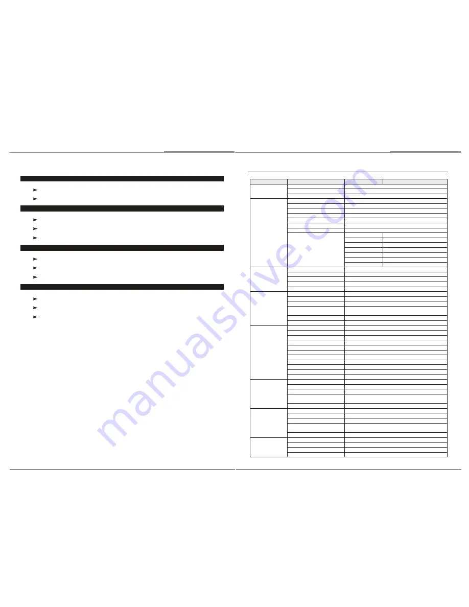
3. OSD MENU
Level 1
Level 2
Level 3
Level 4
INFORMATION
VIDEO FORMAT
Current video format(Display only)
COLOR TEMP
Current color temperature(Display only)
VERSION
Current firmware version(Display only)
VIDEO
EXIT
Return to Level 1
APERTURE
ON / OFF, default: OFF
APT LEVEL
0 ~ 100, default: 80
GAMMA
1.0 ~ 3.0, default: 2.2
SHIFT H
-128 ~ 127, default: 0
SHIFT V
-128 ~ 127, default: 0
COLOR TEMP
6500K / 9300K / USER
COLOR TEMP USER
COPY FROM
6500K/9300K
RED GAIN
0.500 ~ 1.992, default: 1.00
GREEN GAIN
0.500 ~ 1.992, default: 1.00
BLUE GAIN
0.500 ~ 1.992, default: 1.00
RED BIAS
-128 ~ 127, default: 0
GREEN BIAS
-128 ~ 127, default: 0
BLUE BIAS
-128 ~ 127, default: 0
MODE
EXIT
Return to Level 1
SCAN
NORMAL / OVERSCAN / ZOOM, default: NORMAL
ASPECT
AUTO / 4:3 / 16:9 /, default: AUTO
MONO/COLOR
RGB / MONO / RED / GREEN / BLUE, default: RGB
HV DELAY
ON / OFF, default: OFF
MARKER
EXIT
Return to Level 1
MARKER
ON / OFF, default: OFF
CENTER
ON / OFF, default: ON
ASPECT
OFF / 4:3 / 16:9 / 1.85:1 / 2.35:1 / 13:9 / 14:9 / 15:9,
default: OFF
SAFETY
OFF, 80 ~ 99%, USER, default: 80%
CROSS HATCH
OFF / SMALL / MEDIUM / LARGE, default OFF
AUDIO
EXIT
Return to Level 1
LEFT CHANNEL
1 ~ 16, default: 1
RIGHT CHANNEL
1 ~ 16, default: 2
CHANNEL PRESET
LOCK / UNLOCKED, default: UNLOCKED
LEVER METER
ON / OFF, default: OFF
BACKGROUND
ON / OFF, default: OFF
DECAY
FAST / MEDIUM / SLOW, default: MEDIUM
DISPLAY CHANNELS
1 ~ 16, default: 8
DISP FILTER
ALL / ACTIVE, default: ALL
COLUMNS
DUAL / QUAD, default: DUAL
DISP TPYE
OVERLAY / OVERLAP, default: OVERLAP
WAVEFORM
EXIT
Return to Level 1
WAVEFORM
ON / OFF, default: OFF
SIZE
SMALL / MEDIUM / LARGE, default MEDIUM
POSITION
LEFT TOP / LEFT BOT / RIGHT TOP / RIGHT BOT,
default RIGHT BOT
DISP TYPE
OVERLAY / OVERLAP, default: OVERLAY
VECTORSCOPE
EXIT
Return to Level 1
VECTORSCOPE
ON / OFF, default: OFF
SIZE
SMALL / MEDIUM / LARGE, default: MEDIUM
POSITION
LEFT TOP / LEFT BOT / RIGHT TOP / RIGHT BOT,
default: LEFT BOT
DISP TYPE
OVERLAY / OVERLAP, default: OVERLAY
REMOTE
EXIT
Return to Level 1
PIN 1
R TALLY(fixed)
PIN 2
G TALLY(fixed)
PIN 3
default: R ONLY


