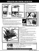
Electrical Connections & Wiring
(Refer fig 1.2)
Wiring is to be carried out only when the switch is mounted and voltage free.
(a) Remove the top cover by unscrewing the black screw.
(b) Pass the cable through the cable gland and connect the wiring.
(c) Basically there are two connection as shown in the figure 1.2 one for
Line and another for Motor. Each has three wires for three phase. Please
ensure appropriate connection of phase wires. Two earthing screws are
provided to connect earthing wires from line and motor.
Certificate No.:
FM 72815
Kaustubha Udyog
7, Parichaya Society, 1000/6D, Navi Peth, Pune 411 030 INDIA
Tel. : +91-(0) 20 - 24332124 / 24321053
Fax : +91-(0) 20 - 25460486 / 24332124
Email : [email protected]
Website : http://www.orion-instruments.com
BULLETIN NO. : KA041220
AN ISO9001:2000 COMPANY
Mounting
Please refer Fig. 1.1
1. Pressure switches can be mounted directly
on process connection 1/2”BSP F nut with
external size of 27 mm A/F.
2. In case, any other process connection is
required then the same can be achieved
using adaptor.
3. Please don't tighten the switch by holding
the top cover. Use appropriate spanner for
turning the process connection nut.
Set Point Adjustment:
Refer fig 1.2
Adjustment is to be carried out only when the switch is mounted,
under pressure and voltage free
a. Remove the top cover.
b. Decide the cut-in (lower) pressure (P1) and cut-out (upper)
pressure (P2). (Pressure switch is closed when the pressure is
between pressure P1 and P2.)
c. Turn the Range nut and differential nut to extreme top position.
d. Apply the desired cut-in pressure (P1) to pressure port.
e. Turn the Range nut slowly till contacts changeover.
f. Turn the differential nut to the extreme positive end (bottom
position)
g. Apply the desired cut-out (upper) pressure (P2) to pressure port.
h. Turn the differential nut till the contacts changeover.
i. Some minor adjustment will be required to achieve the exact
cutin (lower) / output (higher) point, which can be checked with
the help of proper pressure measurement device.
j. Replace the polymer cover after the adjustment of cut-in and cut-
out point is achieved.
Fig. 1.2
Differential Nut
For
Motor
For
Line
Earth
Screw
Relief
Valve
104
1
0
0
60
Range
Operating Nut
60.0
4.5
7.0
7
0
.0
1
1
9
.0
3
7
.5
38.0
63.4
44.8
28.0
On
Off
Screw for Cover
On/Off Knob
Cable
Gland
Cable Entry
Screw
Hex. A/F 27
(for Fitting the Switch)
13.0
40.0
61.0
103.5
Pressure Port
1/2" BSP Female
Pr. Relief Valve
INSTALLATION DRAWING
Approx. Dimensions in mm
Fig. 1.1
27
mm
Wrong Method
Correct Method
INSTALLATION AND OPERATING INSTRUCTIONS


