IAP-320 / 320+ User’s Manual
49 ORing Industrial Networking Corp.
4. Also have the relevant information, you can right-click “Properties” to view a specific
property features.
Page 1: ...ser s Manual Version 1 0 Jan 2010 ORing Industrial Networking Corp 4F NO 3 Lane235 Baociao Rd Sindian City Taipei County 23145 Taiwan R O C Tel 886 2 2918 3036 Fax 886 2 2918 3084 Website www oring networking com E mail support oring networking com ...
Page 2: ...3 3 Bottom Panel 8 3 4 Rear Panel 8 Cables and Antenna 9 4 1 Ethernet Cables 9 4 2 100Base T X 10Base T Pin Assignments 9 4 3 Wireless Antenna 10 Management Interface 11 5 1 Explore IAP 320 320 11 5 1 1 AP Tool software 11 5 2 UPnP Equipment 12 5 3 Configuration by Web Browser 14 5 4 About Web Based Management 14 5 5 Main Interface 15 5 5 1 Basic Setting 15 Setting Operation Mode 15 Setting WDS Br...
Page 3: ...ings 34 5 5 3 System Tools 35 Administrator 35 Date Time 36 Configuration 38 Firmware Upgrade 38 Miscellaneous 39 5 5 4 System Status 40 System Info 40 System Log 40 Traffic Statistics 41 Wireless Clients 41 5 5 5 Online Help 42 Technical Specifications 43 APPENDIX A 45 How to configure SNMP MIB and use SNMP in the PCs 45 ...
Page 4: ...on Therefore IAP 320 320 are one of the best communication solutions for wireless application 1 2 Software Features High Speed Air Connectivity WLAN interface support up to 54Mbps link speed connection Highly Security Capability WEP WPA WPA2 Radius TKIP supported Support AP Bridge Repeater AP Client Mode Switch Mode Supported Daisy Chain support to reduce usage of switch ports Secured Management b...
Page 5: ...nstallation AP on DIN Rail Each AP has a DIN Rail kit on rear panel The DIN Rail kit helps AP to fix on the DIN Rail It is easy to install the AP on the DIN Rail Step 1 Slant the AP and mount the metal spring to DIN Rail Step 2 Push the AP toward the DIN Rail until you heard a click sound ...
Page 6: ...AP has another installation method to fix the AP A wall mount panel can be found in the package The following steps show how to mount the AP on the wall Step 1 Remove DIN Rail kit Step 2 Use 6 screws that can be found in the package to combine the wall mount panel Just like the picture shows below ...
Page 7: ...e screws specification shows in the following two pictures In order to prevent the AP from any damage the screws should not larger than the size that used in IAP 320 320 Pozidrive Step 3 Mount the combined AP on the wall IAP 320 ANT ET H1 ET H2 WLAN Fault PWR2 PWR1 ...
Page 8: ...bes the labels that stick on the IAP 320 320 Port Description 10 100 RJ 45 fast Ethernet ports 2 10 100Base T X RJ 45 fast Ethernet ports support auto negotiation Default Setting Speed auto PoE P D Port ETH2 of IAP 320 compliant with IEEE802 3af PoE specifications ANT Reversed SMA connector for high gain external antenna ...
Page 9: ...r and system status When the PoE power links the green LED will be light on 3 LED for PWR1 and system status When the PWR1 links the green LED will be light on 4 LED for PWR2 and system status When the PWR2 links the green LED will be light on 5 LED for Fault Relay When the fault occurs the amber LED will be light on 6 10 100Base T X Ethernet ports IAP 320 contains P D function of PoE 7 LED for Et...
Page 10: ...IP conflict or DHCP or BOOTP server did not respond properly PWR2 Green Red Green On DC power 2 activated Green blinking Device been located Red blinking Indicates an IP conflict or DHCP or BOOTP server did not respond properly Fault Amber On Fault relay Power failure or Port down fail WLAN Green On WLAN activated Blinking WLAN Data transmitted WLAN Strength Green On WLAN signal strength 1 25 2 50...
Page 11: ...tput 1A 24VDC 2 Reset bottom Push the bottom 3 seconds for reset 5 seconds for factory default Reset PWR 2 PWR 1 V2 V2 Relay V1 V1 Reset Button Terminal Block Power 2 Input Relay Output Pin Terminal Block Power 1 Input Bottom panel of IAP 320 320 3 4 Rear Panel The rear panel components of IAP 320 320 are showed as below 1 Screw holes for wall mount kit 2 DIN Rail kit Rear panel of IAP 320 320 1 2...
Page 12: ...ype Max Length Connector 10Base T Cat 3 4 5 100 ohm UTP 100 m 328 ft RJ 45 100Base T X Cat 5 100 ohm UTP UTP 100 m 328 ft RJ 45 4 2 100Base T X 10Base T Pin Assignments With 100Base T X 10Base T cable pins 1 and 2 are used for transmitting data and pins 3 and 6 are used for receiving data RJ 45 Pin Assignments Pin Number Assignment 1 TD 2 TD 3 RD 4 Not used 5 Not used 6 RD 7 Not used 8 Not used Th...
Page 13: ...3 RD receive TD transmit 4 Not used Not used 5 Not used Not used 6 RD receive TD transmit 7 Not used Not used 8 Not used Not used Note and signs represent the polarity of the wires that make up each wire pair 4 3 Wireless Antenna A 2 4GHz antenna is used for IAP 320 320 and connected with a reversed SMA connector External antenna also can be applied with this connector ...
Page 14: ...iendly software AP Tool to explore IAP 320 320 on local area network Step 1 Open the AP tool and click Refresh list the AP devices will show on the list Step 2 Choose your access point and it will show the AP attribute Simultaneity you can manual set the AP s IP address User interface of AP Tool Step 3 Click Access via web button it will go to web page ...
Page 15: ...P UI of the computer is connected to the IAP 320 320 go to Control Panel Add or Remove Programs Windows Components Wizard Networking Servers UPnP User Interface and pitch on the UPnP User Interface UPnP configuration page Step 2 At the right below corner of the computer you will find a sign of the UPnP equipment ...
Page 16: ... UPnP equipment then you will find the UPnP equipment in the network neighborhood Step 4 Right click the UPnP equipment to choose Properties it will show as the following pictures Step 5 Right click the UPnP equipment or double click the UPnP equipment to transfer it will go to the web page ...
Page 17: ...ports Internet Explorer 5 0 or later It is Based on Java Applets with an aim to reduce network bandwidth consumption enhance access speed and present an easy viewing screen Note By default IE5 0 or later version does not allow Java Applets to open sockets You need to explicitly modify the browser setting in order to enable Java Applets to use network ports Through the front section s information y...
Page 18: ...uick install the AP Main interface 5 5 1 Basic Setting Setting Operation Mode Operation mode interface The following table describes the labels in this screen Label Description AP This mode provides Access Point services for other wireless clients AP Client The AP Client function provides a 1 to N MAC address mapping mechanism such that multiple stations behind the AP can ...
Page 19: ...es Static LAN to LAN Bridging functionality The static LAN to LAN bridging function is supported through Wireless Distribution System WDS In each mode the IAP 320 320 forwards packet between its Ethernet interface and wireless interface for wired hosts on the Ethernet side and wireless hosts on the wireless side Setting WDS Bridge Mode WDS setting interface This type of wireless link is establishe...
Page 20: ...bels in this screen Label Description WDS Mode This mode provides Static LAN to LAN Bridging functionality The static LAN to LAN bridging function is supported through Wireless Distribution System WDS Encryption Type Select the type of security for your wireless network WDS Key Fill in the encryption key when Encryption Type is TKIP or AES LAN LAN WDS ...
Page 21: ... different IP in the same network 2 All AP s DHCP Server should set shutdown 3 WDS should set Enable 4 Each AP should have the same setting except Peer Mac Address set to the other s Mac address 5 WEP Key and Channel should be the same and each AP s SSID should be broadcast to see in the other s computer 6 AP s distance should limit to a certainty area WDS Restricted Mode The peer WDS APs are acco...
Page 22: ...etween WDS links links that connect to other AP wireless bridges and an Ethernet port As a standard bridge the AP learns MAC addresses of up to 64 wireless or 128 total wired and wireless network devices which are connected to their respective Ethernet ports to limit the amount of data to be forwarded Only data destined for stations which are known to reside on the peer Ethernet link multicast dat...
Page 23: ...and also one WDS link side can not set Peer Mac Address 1 4 The working principle of Repeater Mode as follows In the figure Repeater is used to extend the range of the wireless infrastructure by forwarding traffic between associated wireless stations and another repeater or AP connected to the wired LAN LAN WDS LAN WDS ...
Page 24: ...nnel Channel 6 is the default channel input a new number if you want to change the default setting All devices on the network must be set to the same channel to communicate on the network Peer AP SSID Only Operation Mode selects AP Client Mode you should enter the peer AP SSID Security options Select the type of security for your wireless network at Security Type None Select for no security WEP Se...
Page 25: ...WEP Encryption Select 64 Bit or 128 Bit WEP encryption 3 Key Type Select ASCII or Hex key type 4 Default Key Index Select one of the keys to be the active key 5 Key 1 4 Input up to four encryption keys ASCII American Standard Code for Information Interchange is a code for representing English letters as numbers from 0 127 Hex digits consist of the numbers 0 9 and the letters A F ...
Page 26: ... Encryption Type Select TKIP or AES encryption 3 Share Key Enter your password The password can be between 8 and 64 characters Security Type WPA WPA2 1 Security Type Select WPA WPA2 2 Radius Server IP Enter the IP address of the RADIUS Server 3 Port Enter the RADIUS port 1812 is default 4 Shared Secret Enter the RADIUS password or key ...
Page 27: ...t 64 Bit or 128 Bit WEP encryption 3 Key Type Select ASCII or Hex key type 4 Default Key Index Select one of the keys to be the active key 5 Key 1 4 Input up to four encryption keys 6 Radius Server IP Enter the IP address of the RADIUS Server 7 Port Enter the RADIUS port 1812 is default 8 Shared Secret Enter the RADIUS password or key ...
Page 28: ...s server validates the request of the Radius customer and return Radius news to back Radius server validates your proof also carry on the authorization So the Radius server received by ISA server responded point out the customer carries proof to be not granted and it means that the Radius server did not authorize you to carry Even if the proof has already passed an identify verification the ISA se...
Page 29: ...Client The Basic setting AP Client Client page is mainly set the client which through the SSID and Security to connect to other AP In this mode the Security Type should be the same with the AP Server The principle of the AP Client Client mode shows in the following pictures ...
Page 30: ...ss the AP normally a valid IP address of your LAN should be specified to the LAN interface The default IP setting is DHCP server Obtain an IP address automatically The following table describes the labels in this screen Label Description Obtain an IP address automatically Select this option if you would like to have an IP address automatically assigned to the IAP 320 320 by DHCP server in your net...
Page 31: ...input another new DNS server Alternate DNS There is a default DNS server and you can input another new DNS server Setting DHCP Server The following table describes the labels in this screen Label Description DHCP Server Enable or Disable the DHCP Server function Enable the AP will be the DHCP server on your local network Start IP Address The dynamic IP assign range Low IP address is the beginning ...
Page 32: ...work that are receiving dynamic IP addresses from the IAP 320 320 5 5 2 Advanced Setting Wireless The following table describes the labels in this screen Label Description Beacon Interval The default value is 100 The Beacon Interval value indicates the frequency interval of the beacon A beacon is a packet broadcast by the AP to synchronize the wireless network 50 is recommended in poor reception D...
Page 33: ... a particular receiving station and negotiates the sending of a data frame After receiving an RTS the wireless station responds with a Clear to Send CTS frame to acknowledge the right to begin transmission Xmit Power This value ranges from 1 100 percent default value is 100 percent A safe increase of up to 60 percent would be suitable for most users Higher power settings are not recommended for us...
Page 34: ... channel but slower to switch than the fixed channel mode Fixed channel Roaming group must be required the same wireless channel but faster to switch than the Standard mode Signal Threshold for Roaming Roaming signal threshold setting When signal below this value AP will roaming to another client target which the same SSID security option and signal strongest within the environment This value just...
Page 35: ...ddresses that are in the selected filter Connected Clients This list will display the wireless MAC addresses that linked with AP MAC Address MAC addresses need to be added to or clear from MAC filter list Apply Click Apply to set the configurations System Event When the AP event triggered the notification procedure will be performed according to the type of the event Which notification would be pe...
Page 36: ...NMP server The Syslog will record the event locally and may send the log remotely to a Syslog server If serious event occurred such as the power failure or link down the fault LED will be switched on as warning Email Settings The following table describes the labels in this screen Label Description SMTP Server Simple Message Transfer Protocol enter the backup host to use if primary host is unavail...
Page 37: ...rogram that runs on the access point The agent provides management information to the NMS by keeping track of various operational aspects of the AP system Turn on to open this service and off to shutdown it SNMP Trap Server 1 4 Specify the IP of trap server which is the address to which it will send traps AP generates Community Community is essentially password to establish trust between managers ...
Page 38: ... can change the username and password The new password must be typed twice to confirm the default Name and Password is admin and The following table describes the labels in this screen Label Description Old Name This field displays the old login name It s read only The default value of login name is admin Old Password Before making a new setting you should provide the old password for a verify che...
Page 39: ...er choose the HTTPS protocol Port Corresponding to the Web protocol there is a default port HTTP 80 HTTPS 443 And you can enter another number which should be in range of 1 65535 Web Access Control Choose the checkbox of the Wired and Wireless you can visit the web page through the mode you choose UPnP Pitch on Enable and the UPnP will display in the right behind corner HTTPS HTTP over SSL is a We...
Page 40: ...ime manually Time Zone Select the time zone manually Get Current Date Time from Browser Click this button you can set the time from browser NTP Enable or disable NTP function to get the time from the NTP server NTP Server 1 The initial choice about NTP Server NTP Server 2 The second choice about NTP Server Synchronize Set the time and the AP s time synchronize with the NTP Server at the time ...
Page 41: ...ck on Browse to browse the local hard drive and locate the system file to be used Click Upload when you have selected the file to be loaded back onto the AP Restore Default Settings You may also reset the IAP 320 320 back to factory settings by clicking on Restore Default Settings Make sure to save the unit s settings before clicking on this button You will lose your current settings when you clic...
Page 42: ...irmware After the upgrade is done successfully the access point will reboot and get revalidated Notice DO NOT POWER OFF THE AP OR PRESS THE RESET BUTTON WHILE THE FIRMWARE IS BEING UPGRADED Miscellaneous If you want restart the access point through the Warm Reset click Restart Now to restart the AP ...
Page 43: ...his page displays the current information for the IAP 320 320 It will display model name as well as firmware version Ethernet Wireless info and device time System Log The system log tracks the important events and setting changes of the AP If the AP is rebooted the logs are automatically cleared ...
Page 44: ...rk traffic statistics for both received and transmitted packets through the Ethernet port and wireless connections associated with the AP Simultaneity the traffic counter will reset by the device rebooting Wireless Clients This page of the list displays the Mac Address of the wireless clients connected Current TX Rate is corresponding to the Transmission Rate in the Advanced Setting Wireless pages...
Page 45: ...IAP 320 320 User s Manual ORing Industrial Networking Corp 42 5 5 5 Online Help Click on any item in the Online Help screen for more information ...
Page 46: ...ace Operating Mode AP Bridge Repeater AP Client Client Antenna Connector Reverse SMA Radio Frequency Type DSSS Modulation IEEE802 11b CCK DQPSK DBPSK IEEE802 11g OFDM with BPSK QPSK 16QAM 64QAM Frequency Band US America FCC 2 412 2 462 GHz 11channels EU Europe CE ETSI 2 412 2 472 GHz 13channels JP Japan 2 412 2 484 GHz 13Channels Transmission Rate IEEE802 11b 1 2 5 5 11 Mbps IEEE802 11g 6 9 12 18 ...
Page 47: ...Input Voltage Dual power inputs PWR1 2 12 48VDC in 6 pin Terminal Block Reverse Polarity Protection Present Power Consumption 6 Watts Environmental Operating Temperature 10 to 55o C Storage Temperature 40 to 85o C Operating Humidity 5 to 95 non condensing Mechanical Dimensions W x D x H 52 mm W x 106 mm D x 144 mm H Casing IP 30 protection Regulatory Approvals Regulatory Approvals FCC Part 15 CISP...
Page 48: ...MP Syslog and input the IP address of the PC used for SNMP trap server Step 2 In the PC you should setup the SNMP trap server This here we use MG SOFT for example 1 The location of the License should configure right during the process of the installation 2 After the installation click into MIB Compile to add the MIB files for example the Oring 802 11a b g and no PoE FW and save the configuration ...
Page 49: ...t the list of MIB then select the ORING ABG 2Port AP MIB which in the MIB Modules to add in the Loaded MIB modules 4 Click into Query list in the MIB Brower and input the IP address of the AP in the Remote SNMP agentÆ click Apply there is an alarm box which let you enter the right community ...
Page 50: ...IAP 320 320 User s Manual 47 ORing Industrial Networking Corp 5 After all the settings you can see the information about the Oring AP in the MIB Tree ...
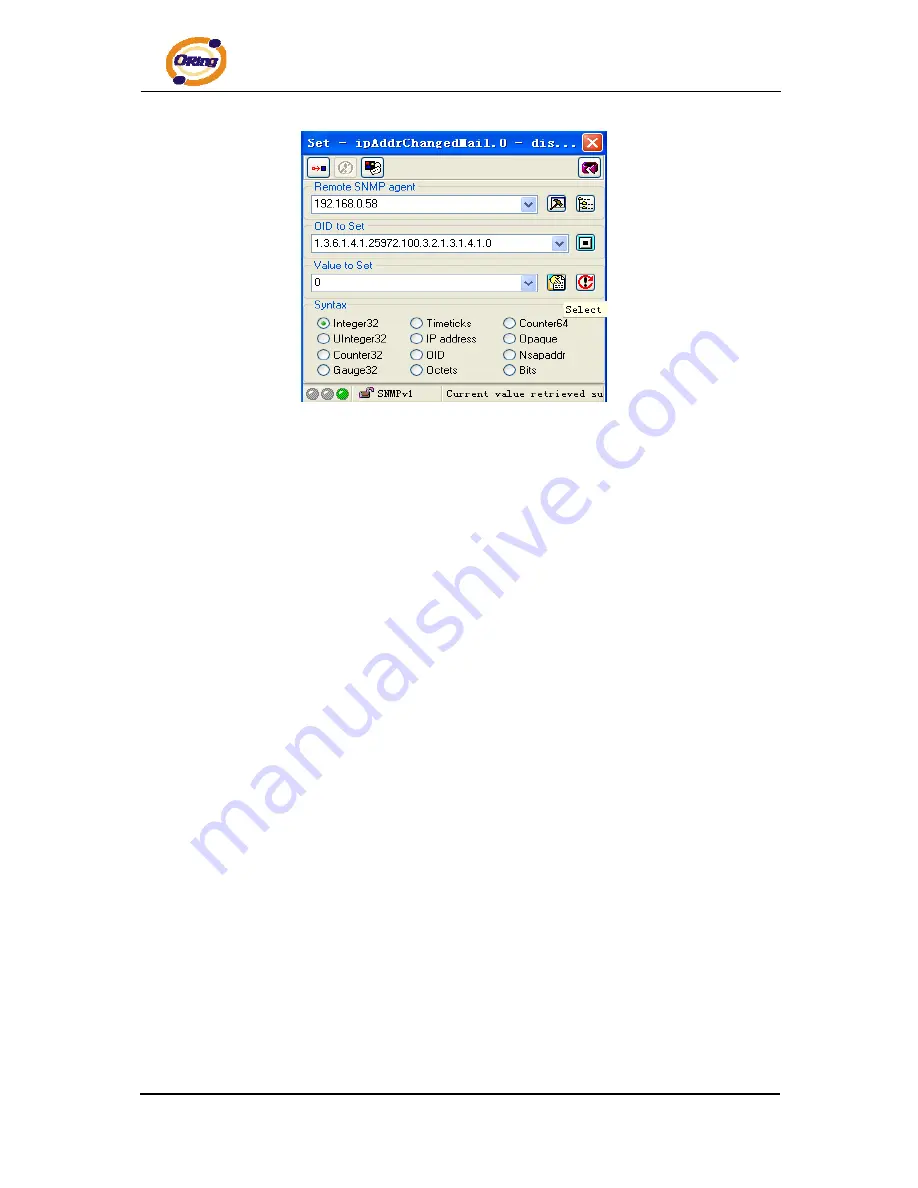
Page 51: ...o shows the basic information of the AP To apSignalStrengthInfo as an example right click select Get on access to the Signal Strength information Shows in SNMP Shows in the web page Response binding 1 apSignalStrengthInfo 0 octet string 100 31 30 30 hex Signal Strength 100 3 The apEvent shows the same content with the page of the System Event and you can also configure the options To PAddrChangedM...
Page 52: ...IAP 320 320 User s Manual 49 ORing Industrial Networking Corp 4 Also have the relevant information you can right click Properties to view a specific property features ...