


20
●
Are the driver’s mounting screws and power-terminal screws tight-
ened securely ?
●
Are any of the power elements and smoothing capacitors inside
the driver giving off a bad smell or showing other abnormalities ?
It is recommended that the following items be checked regularly af-
ter operation.
Should an abnormality be noted, discontinue any use and contact
your nearest Oriental Motor office.
Inspection
●
The driver uses semiconduc-
tor elements, so exercise
due caution when handling
the driver. The driver may
be damaged by the effects
of static electricity, etc.
NOTE
Inspection items
Troubleshooting and corrective actions
During motor operation, the motor or driver may fail to operate prop-
erly due to an error in speed setting or inappropriate connection.
If the motor doesn’t operate properly, refer to this section and take
appropriate action. If the problem persists, contact your nearest
Oriental Motor office.
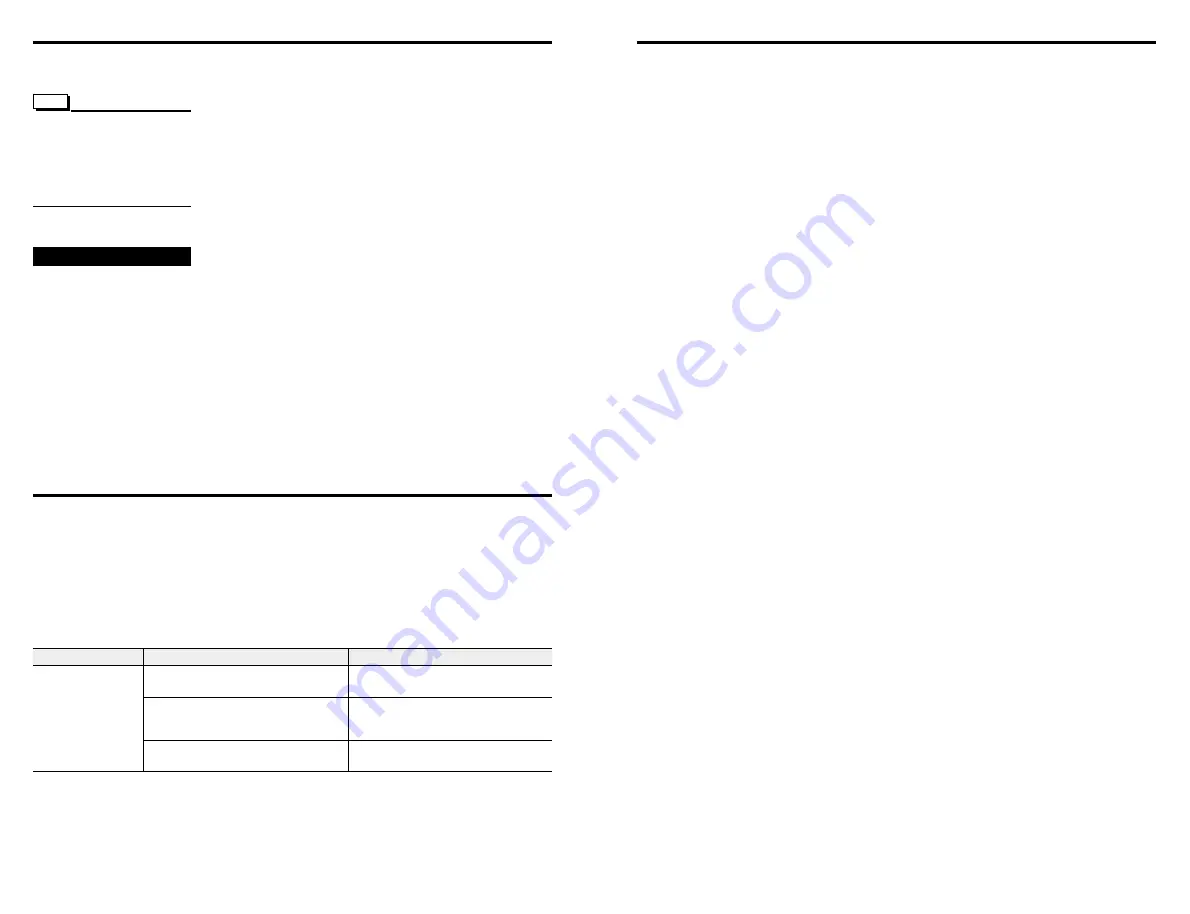
●
Improperly connected motor cable
●
Current setting error.
Setting too small a value reduces motor
torque, resulting in unstable operation
●
The HOFF input is turned ON
Symptom
Possible cause
Corrective action
●
Check again to see whether the driver
and motor are connected properly
●
Check the current setting again
●
Turn the HOFF input to OFF and confirm
that the motor has holding torque
The motor has no
holding torque
The motor can
be moved by hand
5
■
Keep the driver’s heat-sink temperature
at 80°C (176°F) or below during use
The driver doesn’t have a protection function against overheating.
Therefore, depending on the operating conditions (e.g., ambient tem-
perature, operating speed and operating duty), the heat sink may
reach temperatures above 80°C (176°F). Be sure the heat sink’s
saturation temperature doesn’t exceed 80°C (176°F). Failure to do
so may result in damage to the driver.
■
Wiring of I /O cables
●
Wire I / O cables over the shortest possible distances.
●
Provide a minimum distance of 300 mm (11.8 inch) between I / O
cables and inductive loads such as electromagnetic relays, and
power lines (e.g., power-supply cable and motor cable). Do not
wire I / O cables together with power lines in the same duct or con-
duit.
Precautions for use
This section covers the limitations and points to note regarding the
use of this TD Series unit.