

6
|
INSTRUCTIONS FOR USE
OM 402LC
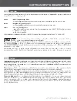
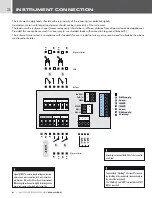
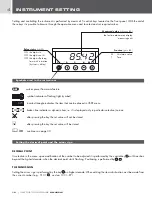
The instrument supply leads should not be in proximity of the incoming low-potential signals.
Contactors, motors with larger input power should not be in proximity of the instrument.
The leads into the instrument input (measured quantity) should be in sufficient distance from all power leads and appliances.
Provided this cannot be secured it is necessary to use shielded leads with connection to ground (bracket E).
The instruments are tested in compliance with standards for use in industrial area, yet we recommend to abide by the above
mentioned principles.
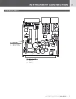
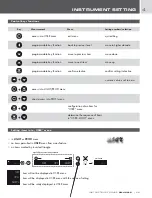
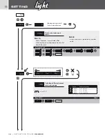
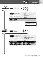
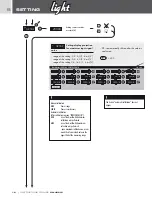
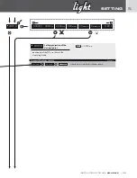
INSTRUMENT CONNECTION
3
14 15 16 17
EXT
. 1
EXT
. 3
EXT
. 2
+ -
5
8 9 10
L
N
SUPPL
Y
E
1 2 3
11 12 13
5 6 7
IV V
VI
III
II I
L4
L3
L2
L1
RxD/L+
TxD/L-
GND
AO-I
AO-U
GND
4
E 1
C 2
E 2
C 1
Relays
SSR
Open collector
Open collector
C 3
E 4
C 4
E 3
ABC
D
E
F
G
H
DMS supply
Shielding
Sense
-
DMS supply
+
+
+
Sense
INPUT
INPUT
-
-
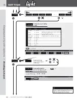
Signal „SENSE“ measures supply voltage on tension-
meter upon 6-wire connection, for 4-wire connection
join brackets B+C and F+G directly on the instrument.
Whenusing the instrument in highly disturbing enviro-
nemnt we recommend using 4-wire connection.
!
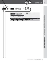
Grounding on terminal block 3 has to be connected
at all times
!
Terminal block “Shielding” is designed for connect-
ing shielding of the supply lead (connected only on
the side of the instrument).
The “Shielding” and “GND” terminal blocks MUST
NOT be connected
!


