


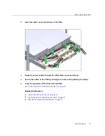


Connecting Data and Management Cables
Segment
Pin
Signal
Note
P9
5.0V
P10
Gnd
Second mate
P11
Reserved
Should be grounded
P12
Gnd
First mate
P13
12.0V
Pre-charge, second mate
P14
12.0V
P15
12.0V
Related Information
■
“Rear Panel Components (Installation)” on page 13
■
“Cabling Requirements” on page 51
■
“Connecting Data and Management Cables” on page 58
Connecting Data and Management Cables
After you have connected these cables, see
“Powering On the Server for the First
before connecting the AC power cords.
■
“Connect the SER MGT Cable” on page 58
■
“Connect the NET MGT Cable” on page 60
■
“Connect Ethernet Network Cables” on page 61
■
“Connect Other Data Cables” on page 62
Related Information
■
“Front Panel Components (Installation)” on page 12
■
“Rear Panel Components (Installation)” on page 13
■
“Cabling Requirements” on page 51
■
“Identifying Ports” on page 52
Connect the SER MGT Cable
The SP serial management port is labeled SER MGT. Use the SER MGT port
only
for server
management. This port is the default connection between the SP and a terminal or a computer.
58
SPARC T7-1 Server Installation Guide • October 2015
Summary of Contents for SPARC T7-1
Page 1: ...SPARC T7 1 Server Installation Guide Part No E54979 01 October 2015 ...
Page 2: ......
Page 8: ...8 SPARC T7 1 Server Installation Guide October 2015 ...
Page 20: ...20 SPARC T7 1 Server Installation Guide October 2015 ...
Page 50: ...50 SPARC T7 1 Server Installation Guide October 2015 ...
Page 64: ...64 SPARC T7 1 Server Installation Guide October 2015 ...
Page 84: ...84 SPARC T7 1 Server Installation Guide October 2015 ...


