background image

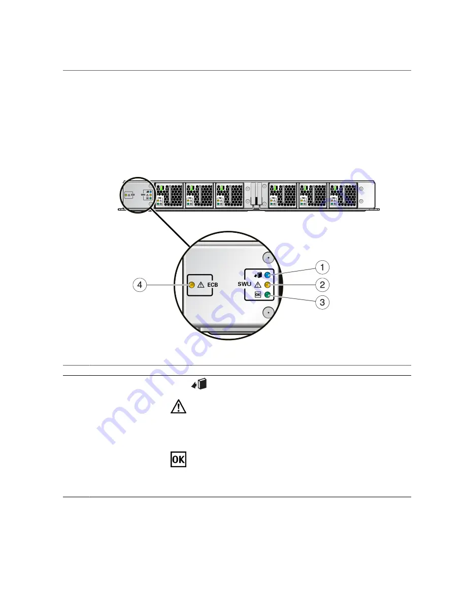
Switch Unit LEDs

“Understanding Server Configurations and Failover Behavior” on page 79

Switch Unit LEDs

No.

LED

Icon

Description

1

Ready to Remove (blue)

Indicates that a switch unit can be removed during a hot-service

operation.

2

Service Required LED

(amber)

Indicates that service is required.

The 

fmadm faulty

 command provides details about any faults that

cause this indicator to light.

Under some fault conditions, individual component fault LEDs are

illuminated in addition to the Service Required LED.

3

OK LED (green)

Indicates these conditions:

Off

 – System is not running in its normal state. System power

might be off. The SP might be running.

Steady on

 – System is powered on and is running in its normal

operating state. No service actions are required.

190

SPARC M8 and SPARC M7 Servers Service Manual • September 2017

Summary of Contents for SPARC M7

Page 1: ...SPARC M8 and SPARC M7 Servers Service Manual Part No E55215 06 September 2017 ...

Page 2: ......

Page 3: ...f information management applications It is not developed or intended for use in any inherently dangerous applications including applications that may create a risk of personal injury If you use this software or hardware in dangerous applications then you shall be responsible to take all appropriate fail safe backup redundancy and other measures to ensure its safe use Oracle Corporation and its af...

Page 4: ...n des informations Ce logiciel ou matériel n est pas conçu ni n est destiné à être utilisé dans des applications à risque notamment dans des applications pouvant causer un risque de dommages corporels Si vous utilisez ce logiciel ou ce matériel dans le cadre d applications dangereuses il est de votre responsabilité de prendre toutes les mesures de secours de sauvegarde de redondance et autres mesu...

Page 5: ...23 Switch Chassis Rear Components SPARC M7 16 25 DIMM and eUSB Locations in a CMIOU 27 Supported Storage Devices 28 Understanding Server Cooling Zones 29 CMIOU Chassis Cooling Zones 29 Switch Chassis Cooling Zones 31 Component Service Task Reference 32 Detecting and Managing Faults 35 Checking for Faults 35 Identify Faulted Components 36 Identify Disabled Components 38 Component Oracle ILOM State ...

Page 6: ...ver Serial Number 60 Locate the Server 61 Prevent ESD Damage 61 Attach an Antistatic Wrist Strap 62 Prepare a Component for Return to Oracle 64 Controlling the Server and Domains 67 Log In to Oracle ILOM Service 67 Prepare a Component for Removal 68 Removing Power From the Server or Domain 69 Prepare to Power Off the Server or Domain 69 Power Off the Server or Domain Oracle ILOM 70 Switch Off PDU ...

Page 7: ...6 85 Mixed CMIOU Configurations 86 CMIOU Redundancy 88 SPARC M8 CMIOU Label 89 CMIOU Indicators and LEDs 90 Prepare a CMIOU for Removal 91 Unseat a CMIOU 93 Remove a CMIOU 95 Return a CMIOU to Oracle 98 Reseat a CMIOU 101 Install a CMIOU 102 Servicing DIMMs 105 DIMM Configuration 106 DIMM Names 108 Determine Which DIMM Is Faulty Oracle ILOM 109 Determine Which DIMM Is Faulty LEDs 109 DIMM Configur...

Page 8: ...allation Order Guidelines 145 Card Installation Bottom CMIOU Chassis Servers With Multiple PDomains 146 Card Installation Bottom CMIOU Chassis SPARC M7 With One PDomain 147 Card Installation Top CMIOU Chassis SPARC M7 16 148 PCIe Card Carrier LEDs and Controls 149 Locate a PCIe Card in the Server 150 Prepare a PCIe Card For Removal 151 Remove a PCIe Card Carrier and Card From the Server 156 Instal...

Page 9: ...s 190 Prepare a Switch Unit for Removal 191 Unseat a Switch Unit 192 Remove a Switch Unit 194 Reseat a Switch Unit 196 Install a Switch Unit 197 Servicing PDECBs 199 Remove a PDECB 200 Install a PDECB 202 Servicing eUSB Disks 203 Remove an eUSB Disk 203 Install an eUSB Disk 205 Servicing a CMIOU Chassis Fan Cable Assembly 207 Remove a Fan Cable Assembly 207 Install a Fan Cable Assembly 212 Servici...

Page 10: ...C Connections 253 Prepare a PDU for Removal 254 Remove a PDU 256 Install a PDU 262 Servicing the CMIOU Chassis 269 Remove a CMIOU Chassis 269 Install a CMIOU Chassis 275 Servicing the Switch Chassis 277 Remove a Switch Chassis 277 Install a Switch Chassis 283 Servicing SP Internal Interconnect Assemblies 285 Remove an SP Internal Interconnect Assembly 286 Install an SP Internal Interconnect Assemb...

Page 11: ...nstall an Internal Interconnect Assembly 302 Servicing External Interconnect Assemblies 305 External Interconnect Assembly Configuration 306 Remove an External Interconnect Assembly 307 Install an External Interconnect Assembly 311 Glossary 317 Index 323 11 ...

Page 12: ...12 SPARC M8 and SPARC M7 Servers Service Manual September 2017 ...

Page 13: ... A basic understanding of the UNIX command line virtualization technologies and networking and disk storage concepts Product Documentation Library Documentation and resources for this product and related products are available at http www oracle com goto m8 docs and http www oracle com goto m7 docs Feedback Provide feedback about this documentation at http www oracle com goto docfeedback Using Thi...

Page 14: ...14 SPARC M8 and SPARC M7 Servers Service Manual September 2017 ...

Page 15: ...onents SPARC M7 16 on page 19 View components accessed from the CMIOU chassis CMIOU Chassis Front Components on page 20 CMIOU Chassis Rear Components on page 21 View components accessed from the switch chassis SPARC M7 16 server only Switch Chassis Front Components SPARC M7 16 on page 23 Switch Chassis Rear Components SPARC M7 16 on page 25 View DIMM locations and numbering DIMM and eUSB Locations...

Page 16: ...n page 79 Server Front Components SPARC M8 8 and SPARC M7 8 Servers No Description Links 1 Bottom CMIOU chassis CMIOU Chassis Front Components on page 20 Related Information CMIOU Chassis Front Components on page 20 CMIOU Chassis Rear Components on page 21 16 SPARC M8 and SPARC M7 Servers Service Manual September 2017 ...

Page 17: ... Rear Components SPARC M8 8 and SPARC M7 8 Servers No Description Links 1 Bottom CMIOU chassis CMIOU Chassis Rear Components on page 21 Related Information CMIOU Chassis Rear Components on page 21 CMIOU Chassis Front Components on page 20 Identifying Components 17 ...

Page 18: ...escription Links 1 Top CMIOU chassis CMIOU Chassis Front Components on page 20 2 Switch chassis Switch Chassis Front Components SPARC M7 16 on page 23 3 Bottom CMIOU chassis CMIOU Chassis Front Components on page 20 18 SPARC M8 and SPARC M7 Servers Service Manual September 2017 ...

Page 19: ...Server Rear Components SPARC M7 16 Related Information Server Rear Components SPARC M7 16 on page 19 Server Rear Components SPARC M7 16 Identifying Components 19 ...

Page 20: ...SPARC M7 16 on page 18 CMIOU Chassis Front Components Access these components from the front of the server These components are not part of the chassis You must remove these components to access the chassis No Description Links 1 Front indicator panel 1 Servicing the Front Indicator Panel on page 217 2 Fan modules 8 Bottom CMIOU chassis Left side top to bottom FM_6 FM_4 FM_2 FM_0 Servicing Fan Mod...

Page 21: ..._N_8_LI slot IT_1 II_W_248 slot IT_2 II_N_8_RI slot IT_3 II_N_8_RO slot IT_4 Servicing Internal Interconnect Assemblies on page 297 4 SP internal interconnects 1 per CMIOU chassis II_CMIOU_SP slot CMIOU SP IT_5 Servicing SP Internal Interconnect Assemblies on page 285 5 Power supplies 6 per CMIOU chassis Bottom CMIOU chassis top to bottom PS5 PS0 Top CMIOU chassis top to bottom PS15 PS10 Servicing...

Page 22: ...ponents No Description Links 1 Rear indicator panel 1 This component is part of the power module Bottom CMIOU chassis ROPNL0 Servicing Power Modules on page 235 22 SPARC M8 and SPARC M7 Servers Service Manual September 2017 ...

Page 23: ...e Cards on page 141 5 SPs 2 bottom CMIOU chassis left to right SPARC M8 8 and SPARC M7 8 servers SP0 SP1 SPPs 4 SPARC M7 16 server Bottom CMIOU chassis left to right SPP0 SPP1 Top CMIOU chassis left to right SPP2 SPP3 Servicing SPs on page 117 6 PDECBs 8 Bottom CMIOU chassis top to bottom PDECB7 PDECB0 Top CMIOU chassis top to bottom PDECB21 PDECB14 Servicing PDECBs on page 199 7 SP tray 1 Servici...

Page 24: ... IT_18 slot IT_10 XI_N_4_B2T_S slot IT_19 slot IT_12 External interconnects left to right bottom CMIOU chassis slot switch chassis slot XI_N_4_T2B_S slot IT_0 slot IT_7 XI_N_4_T2B_S slot IT_1 slot IT_9 II_W_4 slot IT_2 XI_N_4_T2B_S slot IT_3 slot IT_11 XI_N_4_T2B_S slot IT_4 slot IT_13 Servicing External Interconnect Assemblies on page 305 3 SP internal interconnect 1 II_CMIOU_SP top CMIOU chassis...

Page 25: ...lies 4 top to bottom PS9 PS6 Servicing Power Supplies on page 165 Related Information Switch Chassis Rear Components SPARC M7 16 on page 25 Switch Chassis Rear Components SPARC M7 16 Access these components from the rear of the server These components are not part of the chassis You must remove these components to access the chassis Identifying Components 25 ...

Page 26: ...iption Links 1 Rear indicator panel 1 This component is part of the power module ROPNL1 Servicing Power Modules on page 235 2 AC inputs 1 strip 4 outlets Servicing Power Modules on page 235 26 SPARC M8 and SPARC M7 Servers Service Manual September 2017 ...

Page 27: ...Ps on page 117 6 PDECBs 6 top to bottom PDECB13 PDECB8 Servicing PDECBs on page 199 7 SP tray 1 Servicing SP Trays on page 243 Related Information Switch Chassis Front Components SPARC M7 16 on page 23 DIMM and eUSB Locations in a CMIOU DIMMs and a single eUSB disk are located in each of the CMIOUs This figure shows a CMIOU with all of the DIMM slots populated with DIMMs All of the DIMM slots must...

Page 28: ...Configuration on page 106 Supported Storage Devices The server supports these storage devices through FC iSCSI NAS or IB protocols SAN attached FC arrays ZFS appliances The server supports solid state storage add in cards in addition to these types of tape backup and restore devices TCP IP 28 SPARC M8 and SPARC M7 Servers Service Manual September 2017 ...

Page 29: ...er rack Note For information about the number of power supplies that must remain in a system for proper cooling see Servicing Power Supplies on page 165 CMIOU Chassis Cooling Zones on page 29 Switch Chassis Cooling Zones on page 31 Related Information Preparing for Cooling in SPARC M8 and SPARC M7 Servers Installation Guide CMIOU Chassis Cooling Zones The CMIOU chassis has two cooling zones In one...

Page 30: ...zone Servicing CMIOUs on page 83 2 CMIOU power supply cooling zone Servicing Fan Modules CMIOU Chassis on page 179 and Servicing Power Supplies on page 165 Related Information Switch Chassis Cooling Zones on page 31 30 SPARC M8 and SPARC M7 Servers Service Manual September 2017 ...

Page 31: ...pushes air through a single switch unit from the front of the server and exhausts it at the rear of the server In the other cooling zone four fan modules push air through the power supplies and exhaust it through the chimney to the SPs and directly out the rear of the chassis No Description Link 1 Main switch unit cooling zones 1 through 6 Servicing Switch Units on page 189 Identifying Components ...

Page 32: ... 105 eUSB disks 1 per CMIOU Not applicable Servicing eUSB Disks on page 203 Fan modules CMIOU chassis 8 per chassis System Cooling Fans Fan_x Servicing Fan Modules CMIOU Chassis on page 179 Fan modules switch chassis 36 per chassis 6 per switch unit System Cooling Fans Fan_x Servicing Fan Modules CMIOU Chassis on page 179 Servicing Fan Modules Switch Chassis on page 183 Front indicator panel 1 per...

Page 33: ...C M8 8 and SPARC M7 8 servers 2 per CMIOU chassis System Other_Removable_Devices Service_Processors Service_Processor_x Servicing SPs on page 117 SPs SPARC M7 16 2 per switch chassis System Other_Removable_Devices Service_Processors Service_Processor_x Servicing SPs on page 117 SPPs SPARC M7 16 only 2 per CMIOU chassis 4 total System Other_Removable_Devices Proxy_Service_Processors Proxy_Service_P...

Page 34: ...34 SPARC M8 and SPARC M7 Servers Service Manual September 2017 ...

Page 35: ... component requires service replace it Performing Advanced Troubleshooting on page 50 3 Manage faults following a service procedure If a service procedure has cleared the fault ensure that the server is now operational If a fault remains following a service procedure clear it manually Verify That a Fault Has Been Cleared on page 54 4 Contact technical support if the problem persists https support ...

Page 36: ... View on page 44 Identify Faulted Components The fmadm faulty displays a list of faults detected by PSH You can run this command from either the host or through the Oracle ILOM fault management shell This example shows how to check for faults through the Oracle ILOM fault management shell You can also check for faults by typing show faulty at the Oracle ILOM prompt Note When you examine the output...

Page 37: ...erial_Number AK00192372 Description A power supply AC input voltage failure has occurred Response The service required LED on the affected power supply and chassis will be illuminated Impact Server will be powered down when there are insufficient operational power supplies Action Please refer to the associated reference document at http support oracle com msg SPT 8000 5X for the latest service pro...

Page 38: ...d Information Log In to Oracle ILOM Service on page 67 Clear a Fault Manually on page 55 Component Names Displayed by Diagnostic Software on page 40 Identify Disabled Components You can run the show disabled command from the Oracle ILOM prompt to identify components that have been disabled either intentionally by a user or because of a fault 1 To identify disabled components at the Oracle ILOM pro...

Page 39: ...abled the component is installed and accessible by the server When Disabled the component is installed but the server cannot access it current_config_state Property can be Enabled Disabled or Degraded When Enabled the component is installed and accessible by the server When Disabled the component is installed but the server cannot access it When Degraded the component has faulted and requires serv...

Page 40: ...z DIMM SPARC M8 8 x is 0 7 y is 0 3 w is 0 or 1 z is 0 or 1 SPARC M7 8 x is 0 7 y is 0 3 w is 0 or 1 z is 0 or 1 SPARC M7 16 x is 0 15 y is 0 3 w is 0 or 1 z is 0 or 1 Fan modules CMIOU chassis SYS FMx Bottom CMIOU chassis x is 0 7 Top CMIOU chassis x is 8 15 Fan modules switch chassis SYS SWUx FMy x is 0 5 y is 0 5 FPGA CMIOU SYS CMIOUx FPGA SPARC M8 8 x is 0 7 SPARC M7 8 x is 0 7 SPARC M7 16 x i...

Page 41: ...Rear Components on page 21for SPARC M8 8 and SPARC M7 8 interconnect names See Switch Chassis Rear Components SPARC M7 16 on page 25 for SPARC M7 16 interconnect names PCIe cards PCIe card carriers SYS CMIOUx PCIEy SYS CMIOUx PCIEy CAR SPARC M8 8 x is 0 7 y is 1 3 SPARC M7 8 x is 0 7 y is 1 3 SPARC M7 16 x is 0 15 y is 1 3 PDECBs SYS PDECBx SPARC M8 8 x is 0 7 SPARC M7 8 x is 0 7 SPARC M7 16 x is ...

Page 42: ... LEDs on page 45 Component Fault Tolerances This topic describes the level of fault tolerance for specific components and provides guidelines for replacing these components when a fault occurs CMIOUs Remove a faulty CMIOU only when a replacement CMIOU is available Install the new CMIOU as quickly as possible within 10 minutes if possible You must prepare a CMIOU before removing it from the server ...

Page 43: ...plies in the switch chassis or five power supplies in the CMIOU chassis There are no restrictions into which slots the power supplies have to be installed You can install them in any of the power supply slots as long as all power supplies are installed SPs Replace one SP in the server at a time You must prepare an SP before removing it from the server Switch units Switch units are configured to wo...

Page 44: ...MIOUs that are powered on or a red X for components that are faulty and need service Refer to the web interface online help for more information about health service definitions For instructions on using the Oracle ILOM chassis view refer to View Status and Faults in Chassis View Oracle ILOM in SPARC M8 and SPARC M7 Servers Administration Guide Related Information Interpreting LEDs on page 44 Iden...

Page 45: ...LED on CMIOU containing faulted DIMM DIMM Fault Remind LED visible only when the CMIOU cover is removed and the DIMM fault remind button is pressed eUSB disks CMIOU Service Required LED on CMIOU containing eUSB disk Fan modules Fan Service Required LED on faulted fan PCIe cards carriers PCIe Fault LED on PCIe carrier PDECBs ECB Fault LED on the CMIOU or switch chassis that contains the faulty PDEC...

Page 46: ...is No LED Icon or Label Description 1 Locator LED and button white You can turn on the Locator LED to identify a particular server When lit the LED blinks rapidly Turn on the Locator LED by pressing the Locator button or in Oracle ILOM type set System locator_indicator on All lights on test Press the Locate button three times within two seconds to test the functionality of the front and rear panel...

Page 47: ...e Slow blinking might indicate that system diagnostics are running or that the server is booting 4 SP LED SP Indicates these conditions Off The server is not receiving power For example the power cords are not connected or the facility power grid circuit breakers are switched off Steady on green One or both of the SPs have initialized and can be accessed through the Oracle ILOM CLI or web interfac...

Page 48: ...On the SPARC M7 16 server rear indicator panels are located on both CMIOU chassis and on the switch chassis The front and rear indicator panel LEDs are always in sync For example if the green OK LED is lit on the front indicator panel the OK LED will also be lit on the rear indicator panel 48 SPARC M8 and SPARC M7 Servers Service Manual September 2017 ...

Page 49: ...on to the System Service Action Required indicator 3 OK LED green Indicates these conditions Off No AC power is present Power might be off Steady on Server is powered on and is running in its normal operating state Short blink every three seconds Server is running in Standby mode and can be quickly returned to full function Slow blink A normal but transitory activity is taking place Slow blinking ...

Page 50: ...iagnose faults using the methods provided in Checking for Faults on page 35 use any of the following methods to diagnose faults on the server Description Links Generate and examine diagnostic information Display Fault Diagnostics Message Buffer on page 50 Examine log files for additional information about the server View Log Files Oracle Solaris on page 51 View Log Files Oracle ILOM on page 51 Gen...

Page 51: ...ntains several message files The most recent messages are in the var adm messages file After a period of time usually every week a new messages file is automatically created The original contents of the messages file are rotated to a file named messages 1 Over a period of time the messages are further rotated to messages 2 and messages 3 and then deleted 1 Log in to Oracle Solaris 2 View log files...

Page 52: ...an also set other Oracle ILOM properties to control various other aspects of POST operations For example you can specify the events that cause POST to run the level of testing POST performs and the amount of diagnostic information POST displays These properties are described in Oracle ILOM Properties That Affect POST Behavior on page 54 If POST detects a faulty component the component is disabled ...

Page 53: ... of keyswitch_state must be normal when individual POST parameters are changed For possible values for the keyswitch_state parameter see Oracle ILOM Administrator s Guide for Configuration and Maintenance at http www oracle com goto ilom docs 3 If the virtual keyswitch is set to normal and you want to define level or verbosity set the respective parameters Syntax set HOST diag property value For e...

Page 54: ...umber of Oracle ILOM commands that you can use to perform host diagnostic tests For details about using these commands refer to the chapter that describes configuring host server management actions in the Oracle ILOM Administrator s Guide for Configuration and Maintenance for your server s version of the Oracle ILOM firmware at http www oracle com goto ilom docs Related Information POST Overview o...

Page 55: ...y on page 55 Clear a Fault Manually When the server detects faults the faults are logged and displayed on the console In most cases after the fault is repaired the corrected state is detected by the server and the fault condition is repaired automatically In cases where the fault condition is not automatically cleared you must clear the fault manually 1 After replacing a faulty component power on ...

Page 56: ...tsp exit reset Servers PDomains PDomain_x HOST Are you sure you want to reset System y Resetting System 5 Clear the fault in the Oracle Enterprise Manager Ops Center software if applicable Clearing a fault with the fmadm acquit command does not clear that fault in the Oracle Enterprise Manager Ops Center software You must manually clear the fault or incident For more information see Marking an Inc...

Page 57: ...1 Attach an Antistatic Wrist Strap on page 62 7 Properly prepare a component for return to Oracle Prepare a Component for Return to Oracle on page 64 Related Information Identifying Components on page 15 Detecting and Managing Faults on page 35 Controlling the Server and Domains on page 67 Understanding Server Configurations and Failover Behavior on page 79 Safety Information For your protection o...

Page 58: ...e instructions Caution Hot surface Avoid contact Surfaces are hot and might cause personal injury if touched Caution Hazardous voltages are present To reduce the risk of electric shock and danger to personal health follow the instructions Related Information Removing Power From the Server or Domain on page 69 Tools Needed for Service on page 58 Tools Needed for Service You will need the following ...

Page 59: ...ust be transferred from an SP or SPP during the replacement of these components No filler panels are required for the PCIe slots as long as the PCIe card carrier is installed Caution To maintain the proper air flow all filler panels and modules must remain in the server unless you remove one to install a functioning component at the same time Related Information Safety Information on page 57 Compo...

Page 60: ...blies Off X Servicing SP Internal Interconnect Assemblies on page 285 Servicing Internal Interconnect Assemblies on page 297 Servicing External Interconnect Assemblies on page 305 PCIe cards On or off Servicing PCIe Cards on page 141 PCIe card carriers On or off Servicing PCIe Cards on page 141 PDECBs On or off X Servicing PDECBs on page 199 PDUs Off X Servicing PDUs on page 253 Power supplies On ...

Page 61: ...EDs one on the front panel and one on the rear panel blink 2 After locating the server with the blinking Locator LED turn it off by pressing the Locator button Note Alternatively you can turn off the Locator LED by setting the value to off Related Information Interpreting LEDs on page 44 Prevent ESD Damage Many components housed within the chassis can be damaged by ESD To protect these components ...

Page 62: ...8 8 or SPARC M7 8 server in your own rack refer to the rack documentation for grounding instructions Related Information Tools Needed for Service on page 58 Safety Information on page 57 Attach an Antistatic Wrist Strap Always wear an antistatic wrist strap connected to a metal surface on the chassis when you work on server components Attach an antistatic wrist strap to one of the ESD grounding ja...

Page 63: ...tic Wrist Strap These grounding jacks accommodate 4 mm 0 16 in banana plug connectors The Sun Rack II 1242 rack contains two ESD grounding jacks one in the front and one in the rear of the rack Preparing for Service 63 ...

Page 64: ... Service on page 58 Prevent ESD Damage on page 61 Prepare a Component for Return to Oracle 1 Refer to the removal procedure for the component for any special repacking and shipping instructions For example refer to Return a CMIOU to Oracle on page 98 for detailed information about packing and shipping a CMIOU 64 SPARC M8 and SPARC M7 Servers Service Manual September 2017 ...

Page 65: ...t contained the replacement component a Using the same material used to pack the replacement component position the component so that it is not free to move b Add any required paperwork or other documentation in the container c Except when packing CMIOUs include any tools that were loaned to you by Oracle Do not place tools inside a container that is being used to return a CMIOU 4 Close the shippi...

Page 66: ...66 SPARC M8 and SPARC M7 Servers Service Manual September 2017 ...

Page 67: ...er or Domain on page 69 Return a component to service after issuing the prepare_to_remove command if needed Return a Component to Service on page 75 Restore power to the server or a domain following a service procedure Returning the Server to Operation on page 73 Related Information Identifying Components on page 15 Detecting and Managing Faults on page 35 Preparing for Service on page 57 Understa...

Page 68: ...to remove See Detecting and Managing Faults on page 35 3 Prepare the component for removal a Light the Ready to Remove LED cd System target name set action prepare_to_remove b Verify that the Ready to Remove LED is lit show System target name health Properties health Offline where target name is as specified for the following components Component Target Name and Values CMIOUs DCUs DCU_x CMIOUy SPA...

Page 69: ...a component you must return the component to service See Return a Component to Service on page 75 Related Information Servicing CMIOUs on page 83 Servicing SPs on page 117 Servicing Switch Units on page 189 Oracle ILOM Paths for SPMs on page 122 Removing Power From the Server or Domain These topics describe different methods for removing power from the chassis Prepare to Power Off the Server or Do...

Page 70: ...p www oracle com goto solaris11 docs Power Off the Server or Domain Oracle ILOM on page 70 Switch Off PDU Circuit Breakers on page 71 Power Off the Server or Domain Oracle ILOM You can use the SP to perform a graceful shutdown of the system This type of shutdown ensures that all of your data is saved and that the system is ready for restart Refer to the SPARC M8 and SPARC M7 Servers Administration...

Page 71: ...rvice on page 67 Prepare to Power Off the Server or Domain on page 69 Restart the Server or Host Oracle ILOM on page 74 Switch Off PDU Circuit Breakers Switch off the circuit breakers to remove power from the server only after you have powered off the server Note The sequence in this section where power is removed first from the even numbered power supplies and then from the odd numbered power sup...

Page 72: ...rver See Power Off the Server or Domain Oracle ILOM on page 70 2 Turn breakers off in the following sequence For SPARC M8 8 and SPARC M7 8 R6 R7 R8 L2 L1 L0 For SPARC M7 16 R4 R5 L5 L4 R0 R1 R2 L8 L7 L6 R6 R7 R8 L2 L1 L0 where R indicates the right PDU from the rear of the server PDU B L indicates the left PDU from the rear of the server PDU A and the number represents the PDU group number Caution...

Page 73: ...fferent location in the rack power is still restored first to the odd numbered power supplies 1 3 5 and then to the even numbered power supplies 0 2 4 See Install a PDU on page 262 for detailed steps for various configurations 1 Notify users that you are preparing to apply power to the server 2 Turn breakers on in the following sequence For SPARC M8 8 and SPARC M7 8 servers L2 L1 L0 R6 R7 R8 For a...

Page 74: ...onsole y n y Starting Servers PDomains PDomain_x HOST console 3 Power on the server or a specific domain To power on all domains at the Oracle ILOM prompt type start System Note On multidomain servers if one of the hosts is already running you cannot use the start System command The server will return a message that the target is already started To power on a specific domain at the Oracle ILOM pro...

Page 75: ...e Removing Power From the Server or Domain on page 69 If the system or domain is not running power_state off and you want to power it on see Returning the Server to Operation on page 73 Related Information Oracle ILOM documentation http www oracle com goto ilom docs Log In to Oracle ILOM Service on page 67 Removing Power From the Server or Domain on page 69 Returning the Server to Operation on pag...

Page 76: ...cessor_x Service_Processor_Module_y Where x is 0 3 and y is 0 or 1 Switch units SPARC M7 16 Other_Removable_Devices Scalability_Switch_Boards Scalability_Switch_Boards_x Where x is 0 5 Related Information Oracle ILOM Paths for SPMs on page 122 Servicing CMIOUs on page 83 Servicing SPs on page 117 Servicing Switch Units on page 189 Prepare a Component for Removal on page 68 Oracle ILOM Service Rela...

Page 77: ...alue of property can be state config expires or script stop System Powers off the host server stop Servers PDomains PDomain_x HOST Powers off a specific domain start System Powers on the host server start Servers PDomains PDomain_x HOST Powers on a specific domain reset System Generates a hardware reset of all hosts reset Servers PDomains PDomain_x HOST Generates a hardware reset on a specific dom...

Page 78: ...78 SPARC M8 and SPARC M7 Servers Service Manual September 2017 ...

Page 79: ...ailover Behavior Two PDomains on page 80 SPARC M8 8 and SPARC M7 8 Configurations and Failover Behavior One PDomain on page 81 SPARC M7 16 Configurations and Failover Behavior on page 81 For information about determining DCU assignment to a PDomain determining CMIOU membership to a DCU or to administer DCUs and CMIOUs refer to the SPARC M8 and SPARC M7 Servers Administration Guide Related Informat...

Page 80: ...ssigned Assigned SPM Pairs DCU_0 CMIOU_0 CMIOU_3 SYS SP0 SPM0 SYS SP1 SPM0 DCU_1 CMIOU_4 CMIOU_7 SYS SP0 SPM1 SYS SP1 SPM1 Oracle ILOM identifies one of the SPMs from each SP as the Active SP to manage activity on the static PDomain The other SPM on the SP runs Oracle ILOM but remains inactive unless the Active SP can no longer manage the hardware In this case the inactive SPM assumes the Active S...

Page 81: ...ilover Behavior A SPARC M7 16 server is divided into four configurable units called DCUs These DCUs have four CMIOUs each Two of the DCUs are in the top CMIOU chassis and two are in the bottom CMIOU chassis You can configure DCUs into one to four PDomains Each CMIOU chassis also has two service processor proxies SPP2 and SPP3 are in the top chassis and SPP0 and SPP1 are in the bottom chassis These...

Page 82: ...eplacing an SPP The switch chassis in the SPARC M7 16 server contains six switch units that allow CMIOUs to communicate with each other The switch chassis also has two SPs SP0 and SP1 that manage system resources Each SP in the switch chassis has a single SPM SPM0 in each SP The SPM that you identify as the Active SP manages system resources unless it can no longer do so in which case the Standby ...

Page 83: ...M8 8 and SPARC M7 8 With Two PDomains on page 84 CMIOU Configurations SPARC M8 8 and SPARC M7 8 With One PDomain on page 85 CMIOU Configurations SPARC M7 16 on page 85 Mixed CMIOU Configurations on page 86 Learn about CMIOU LEDs CMIOU Indicators and LEDs on page 90 Prepare to remove a CMIOU Prepare a CMIOU for Removal on page 91 Replace a CMIOU Remove a CMIOU on page 95 Return a CMIOU to Oracle on...

Page 84: ...nd CMIOU_4 CMIOU_7 in PDomain_1 Note The SPARC M7 8 server with two PDomains is the only SPARC M7 server that can support SPARC M8 CMIOUs SPARC M8 CMIOUs are supported in PDomain_1 CMIOU_4 to CMIOU_7 of the SPARC M7 8 server with two PDomains SPARC M8 CMIOUs are not supported in PDomain_0 CMIOU_0 to CMIOU_3 SPARC M7 CMIOUs are not supported in SPARC M8 8 servers See Mixed CMIOU Configurations on p...

Page 85: ...e PDomain does not support SPARC M8 CMIOUs SPARC M7 CMIOUs are not supported in SPARC M8 8 servers See Mixed CMIOU Configurations on page 86 for more information For information about the PCIe slots that are available in each of these configurations see Understanding PCIe Card Device and Service Paths on page 143 Caution To prevent overheating fill unused CMIOU slots with CMIOU filler panels Relat...

Page 86: ...information For information about the PCIe slots that are available in each of these configurations see Understanding PCIe Card Device and Service Paths on page 143 Caution To prevent overheating fill unused CMIOU slots with CMIOU filler panels Related Information SPARC M7 16 Configurations and Failover Behavior on page 81 Mixed CMIOU Configurations The SPARC M7 8 server configured with two static...

Page 87: ...will continue to run The server will generate an ereport alerting you to the unsupported configuration and the new CMIOUs will not be added to the running PDomain You must fix the unsupported configuration by either removing or disabling the offending CMIOUs before you can restart the PDomain A SPARC M7 8 server with a mixed CMIOU configuration must run a system firmware version that supports both...

Page 88: ...age 85 For example ensure that there are CMIOUs installed in slots CMIOU_0 and CMIOU_1 in a SPARC M8 8 server with one PDomain In this example if one of the CMIOUs has faulted the PDomain will still be able to access the SP through the other CMIOU If there is only one CMIOU is installed a PDomain or DCU the communication link between the SP and the PDomain will be lost if the CMIOU faults or is ta...

Page 89: ...Label The SPARC M8 CMIOUs contain a SPARC M8 label on the left extraction lever SPARC M7 CMIOUs do not have a label Related Information SPARC M8 8 and SPARC M7 8 Configurations and Failover Behavior Two PDomains on page 80 CMIOU Configurations SPARC M8 8 and SPARC M7 8 With Two PDomains on page 84 CMIOU Indicators and LEDs on page 90 Mixed CMIOU Configurations on page 86 Servicing CMIOUs 89 ...

Page 90: ...ides details about any faults that cause this indicator to light Under some fault conditions individual component fault LEDs are illuminated in addition to the Service Required LED 3 OK LED green Indicates these conditions Off CMIOU is not operational System power might be off The SP might be running Steady on CMIOU is powered on and is running in its normal operating state No service actions are ...

Page 91: ...ded antistatic mat Always use an antistatic wrist strap for hardware replacements Note The CMIOU replacement kit includes a plastic cover to protect the CMIOU connectors When you unpack the new CMIOU be sure to set the connector cover aside You must install this cover on the CMIOU that you return to Oracle 1 Determine which CMIOU requires service See Identify Faulted Components on page 36 and CMIO...

Page 92: ...Stopping Servers PDomains PDomain_x HOST 7 Confirm that the host has stopped show Servers PDomains PDomain_x HOST status Servers PDomains PDomain_x HOST Properties status Powered Off 8 Prepare the installed CMIOU for removal set System DCUs DCU_x CMIOU_y action prepare_to_remove where SPARC M8 8 or SPARC M7 8 with two PDomains x is 0 and y is 0 3 or x is 1 and y is 4 7 SPARC M8 8 or SPARC M7 8 wit...

Page 93: ...nnector cover from the connectors on the new CMIOU and set it aside for installation on the old CMIOU connectors Related Information Unseat a CMIOU on page 93 Return a CMIOU to Oracle on page 98 Remove a CMIOU on page 95 Controlling the System Hosts and SPs in SPARC M8 and SPARC M7 Servers Administration Guide Unseat a CMIOU Complete the following steps before you unseat or remove a CMIOU Caution ...

Page 94: ...rd you to disengage the CMIOU connectors from the server panel 2 c Grasp the ejector arms as close to the CMIOU as possible and pull the CMIOU one third to halfway out of the server panel 3 Related Information Remove a CMIOU on page 95 Install a CMIOU on page 102 94 SPARC M8 and SPARC M7 Servers Service Manual September 2017 ...

Page 95: ...wrist strap for hardware replacements Note The CMIOU replacement kit includes a plastic cover to protect CMIOU connectors Install the connector cover on the CMIOU that you return to Oracle 1 Ensure that you have prepared the CMIOU for removal See Prepare a CMIOU for Removal on page 91 2 Unseat the CMIOU See Unseat a CMIOU on page 93 3 Remove the CMIOU from the server a Fold the ejector arms back t...

Page 96: ...f the cover to disengage the cover from the CMIOU While pressing the button grasp the rear edge of the cover and slide it toward the rear of the CMIOU until it stops Lift the cover off 6 Determine your next step a If you are replacing a faulty CMIOU remove all of the DIMMs and PCIe carriers including any installed PCIe cards and transfer them to the new CMIOU See Servicing DIMMs on page 105 and Se...

Page 97: ...Ie cards Servicing PCIe Cards on page 141 eUSB disks Servicing eUSB Disks on page 203 PDECBs Servicing PDECBs on page 199 Related Information Reseat a CMIOU on page 101 Return a CMIOU to Oracle on page 98 Install a CMIOU on page 102 Servicing CMIOUs 97 ...

Page 98: ...ensuring that the connectors are properly protected a Install the protective connector cover which you removed from the replacement CMIOU on the CMIOU that you are returning to Oracle You must install this cover on the CMIOU panel 1 98 SPARC M8 and SPARC M7 Servers Service Manual September 2017 ...

Page 99: ...he protruding end of the CMIOU latch is centered in the window of the inner container panel 2 c Place corrugated sheet on top of the CMIOU with the Top Rear marking on the rear of the chassis facing up Ensure that the corrugated sheet extends over the connector panel 3 2 Close inner container and secure the container with tape a Fold the bottom and top flaps of the inner container over the CMIOU p...

Page 100: ... bottom corner cushions into outer shipping container 2 Insert bottom center cushion on bottom of outer shipping container 3 Position sealed inner shipping container on top of bottom center cushion 4 Insert top center cushion on top of sealed inner shipping container 100 SPARC M8 and SPARC M7 Servers Service Manual September 2017 ...

Page 101: ...terconnects and PDECBS require you to unseat a CMIOU before you perform them After completing those tasks you need to reseat the CMIOU 1 Slide the CMIOU back into the server until the levers begin to engage 2 Press the levers back together toward the center of the CMIOU and then press the levers firmly against the CMIOU to fully seat it into the server The levers should click into place when the m...

Page 102: ... it on Note SPARC M7 CMIOUs are not supported in SPARC M8 8 servers SPARC M8 CMIOUs are not supported in SPARC M7 16 servers or SPARC M7 8 servers containing one static PDomain one to eight CMIOUs SPARC M7 8 servers with two static PDomains are the only SPARC M7 servers that support SPARC M8 CMIOUs and only in PDomain_1 See Mixed CMIOU Configurations on page 86 for more information 1 If you remove...

Page 103: ... they are fully open panel 2 c Insert the CMIOU back into its slot in the server until the levers begin to engage panel 3 d Press the levers back together toward the center of the CMIOU and then press the levers firmly against the CMIOU to fully seat the CMIOU into the server panel 4 The levers should click into place when the module is fully seated in the server 3 Determine your next step Servici...

Page 104: ...ther service procedure connect to the host console then connect to the host and restart it Connect to the host console in a separate terminal session to ensure that you can view all messages reported by the system start Servers PDomains PDomain_x HOST console Are you sure you want to start Servers PDomains PDomain_x HOST console y n y Connecting Servers PDomains PDomain_x HOST console start Server...

Page 105: ...iption Links Understand how to configure DIMMs DIMM Configuration on page 106 Understand DIMM labels or names DIMM Names on page 108 Locate a faulty DIMM Determine Which DIMM Is Faulty Oracle ILOM on page 109 Determine Which DIMM Is Faulty LEDs on page 109 DIMM Configuration Fault Messages on page 112 Replace a DIMM Remove a DIMM on page 112 Install a DIMM on page 114 Related Information Identifyi...

Page 106: ...delines when replacing DIMMs in a CMIOU SPARC M8 8 servers Use either all 32 Gbyte or all 64 Gbyte DDR4 DIMMs SPARC M7 8 and SPARC M7 16 servers Use all 16 Gbyte all 32 Gbyte or all 64 Gbyte DDR4 DIMMs Ensure that all DIMMs in a CMIOU are the same size and type Do not mix 32GB LRDIMMs 4R x 4Gb and 32 GB RDIMMs 2R x 8Gb in the same CMIOU If you are using DIMMs of different capacities in the same ho...

Page 107: ...DIMM Configuration The SPARC M7 CMIOU DIMM locations and the buffer chip BOB and DDR channel CH numbers are as follows Servicing DIMMs 107 ...

Page 108: ...s DIMMs follow the naming convention SYS CMIOUx CM CMP BOByw CHz DIMM with the following values CMIOU number SPARC M8 8 where x is 0 to 7 SPARC M7 8 where x is 0 to 7 SPARC M7 16 where x is 0 to 15 Buffer chip BOB number where y is 0 to 3 and w is 0 or 1 108 SPARC M8 and SPARC M7 Servers Service Manual September 2017 ...

Page 109: ...OU1 CM CMP BOB11 CH1 DIMM SP faultmgmt 0 faults 0 class fault memory dimm SP faultmgmt 0 faults 0 sunw msg id SPSUN4V 8000 CQ SP faultmgmt 0 faults component SYS CMIOU1 CM CMP BOB11 CH1 DIMM SP faultmgmt 0 faults uuid 99209d8f 38ce e9dc 95fd c0200 SP faultmgmt 0 faults timestamp 2014 09 07 13 12 35 The first line of the preceding output shows the CMIOU number buffer chip number and DDR channel num...

Page 110: ...e faulty DIMM See Remove a CMIOU on page 95 4 Locate press and hold the blue Fault Remind button on the CMIOU An illuminated green Fault Remind Power LED indicates that there is power available to light the faulty DIMM LED Any faulty DIMM is identified by an amber LED next to the DIMM slot until you release the button Note If LEDs for two DIMMs light replace both of the DIMMs 110 SPARC M8 and SPAR...

Page 111: ... Remind Power button operate the same way on both CMIOU types 5 Confirm that the DIMM next to the illuminated DIMM Fault LED is the same DIMM that was reported to be faulty by the fmadm faulty command Read the DIMM name text printed on the board next to the slot with the illuminated DIMM Fault LED for example BOB01 CH1 DIMM See Determine Which DIMM Is Faulty Oracle ILOM on page 109 DIMM Names on p...

Page 112: ... CMIOU chassis to access the DIMMs Note Do not mix 32GB LRDIMMs 4R x 4Gb and 32GB RDIMMs 2R x 8Gb in the same CMIOU If you are replacing LRDIMMs with RDIMMs replace all of the DIMMs in the CMIOU Caution Before beginning this procedure ensure that you are familiar with the cautions and safety instructions described in Safety Information on page 57 and the information in DIMM Configuration on page 1...

Page 113: ...e ejector tabs on both sides of the DIMM until the DIMM is released Caution DIMMs and heat sinks on the motherboard might be hot b Grasp the top corners of the faulty DIMM lift it out of its slot and place it on a grounded antistatic mat 4 Repeat the previous step for any other DIMMs that you need to remove 5 Determine your next step If you are replacing a faulty DIMM continue to Install a DIMM on...

Page 114: ...n page 61 2 Ensure that you have removed either the CMIOU containing the faulted DIMM or the CMIOU filler panel See Remove a CMIOU on page 95 3 If you are replacing a faulty DIMM ensure that you have removed it See Remove a DIMM on page 112 4 Unpack the replacement DIMM and place it on a grounded antistatic mat Caution You must install the same size and capacity of DIMMs that are already in the ex...

Page 115: ... the DIMM does not easily seat into the connector check the DIMM orientation 7 Install the CMIOU into the server See Install a CMIOU on page 102 8 Verify that the fault has been cleared and the replaced component is operational See Verify That a Fault Has Been Cleared on page 54 Servicing DIMMs 115 ...

Page 116: ...116 SPARC M8 and SPARC M7 Servers Service Manual September 2017 ...

Page 117: ... and Failover Behavior on page 81 For the location of the SPs and SPPs see CMIOU Chassis Rear Components on page 21 and Switch Chassis Rear Components SPARC M7 16 on page 25 Note Replace a failed SP or SPP as soon as possible Do not remove an SP or SPP until a replacement is available Caution This procedure requires that you handle components that are sensitive to electrostatic discharge This disc...

Page 118: ...page 124 Change Which SPP Is Managing DCU Activity SPARC M7 16 on page 125 Prepare an SP or SPP for removal Prepare to Remove an SP on page 125 Prepare to Remove an SPP SPARC M7 16 on page 129 Replace an SP or SPP Remove an SP or SPP on page 132 Install an SP or SPP on page 136 Related Information Identifying Components on page 15 Detecting and Managing Faults on page 35 Preparing for Service on p...

Page 119: ... a system migration or hardware replacement For information about enabling failover when you initialize TPM see Securing Systems and Attached Devices in Oracle Solaris 11 3 After replacing an SP the SP firmware the host firmware and the configuration will be restored from the existing Active SP to the new SP Note For information about firmware updates and the associated pkg files that could be nee...

Page 120: ...or to light Under some fault conditions individual component fault LEDs are illuminated in addition to the Service Required LED 3 OK LED green Indicates these conditions Off System is not running in its normal state System power might be off Steady on System is powered on and is running in its normal operating state No service actions are required Slow blink A normal but transitory activity is tak...

Page 121: ...information about cabling the network management ports on your server Note The SPARC M8 SP has a SPARC M8 label on its left extraction lever The SPARC M7 SPs do not have a label No Description Links 1 4 SER MGT ports 0 3 The serial ports enable you to connect directly to the SPs and SPPs 5 8 NET MGT ports 0 3 The Ethernet ports enable you to connect the server to your local network so that you can...

Page 122: ... System Other_Removable_Devices Proxy_Service_Processors DCU0 SPP0 SPM0 SPP1 SPM0 Proxy_Service_Processor_0 Service_Processor_Module_0 Proxy_Service_Processor_1 Service_Processor_Module_0 DCU1 SPP0 SPM1 SPP1 SPM1 Proxy_Service_Processor_0 Service_Processor_Module_1 Proxy_Service_Processor_1 Service_Processor_Module_1 DCU2 SPP2 SPM0 SPP3 SPM0 Proxy_Service_Processor_2 Service_Processor_Module_0 Pro...

Page 123: ...LOM firmware version 4 0 x The property will not be available on SPARC M7 servers running earlier versions of the Oracle ILOM firmware Always update your system firmware to latest available and supported version for optimal performance security and stability On an SP type set System DCUs failover manual Related Information Determine Which SP Is Managing System Activity on page 123 Determine Which ...

Page 124: ... SPP0 SPM0 initiate_failover_action none Related Information Understanding Server Configurations and Failover Behavior on page 79 SPARC M8 and SPARC M7 Servers Administration Guide Change Which SP Is Managing System Activity Complete this task to change the current roles of the SP pair For example you might want to change the SP that is currently identified as the Active SP to be the Standby SP if...

Page 125: ...PARC M7 8 servers have two SPs in the CMIOU chassis SPARC M7 16 servers have two SPs in the switch chassis On all servers one SP serves as the Active SP and one serves as the Standby SP The Active SP manages DCU activity and all system resources unless it can no longer do so in which case the Standby SP assumes its role Note Replace only one SP in the system at a time Note If you issue the prepare...

Page 126: ...essor_0 Service_Processor_Module_1 3 For SPARC M8 8 and SPARC M7 8 servers only verify that the PCIe devices are offline For SPARC M8 8 and SPARC M7 8 servers with two PDomains check the state for both SPMs show System Other_Removable_Devices Service_Processors Service_Processor_x Service_Processor_Module_0 state_pcie Properties state_pcie Offline show System Other_Removable_Devices Service_Proces...

Page 127: ... step cd System Other_Removable_Devices Service_Processors Service_Processor_x Service_Processor_Module_0 set action prepare_to_remove This command can take several minutes to complete Determine your next step For SPARC M8 8 and SPARC M7 8 servers with two PDomains perform this step for the second SPM and then go to Step 6 For SPARC M8 8 and SPARC M7 8 servers with one PDomain go to Step 6 For SPA...

Page 128: ...moval show System Other_Removable_Devices Service_Processors Service_Processor_x Service_Processor_Module_0 health Properties health Offline Note For SPARC M8 8 and SPARC M7 8 with two PDomains perform this step for the second SPM 8 Prepare the SP for removal cd System Other_Removable_Devices Service_Processors Service_Processor_x set action prepare_to_remove This command powers off the SP and lig...

Page 129: ...ot but if you do not physically install an SPP into the slot you must issue the return_to_service command for the SPP See Return a Component to Service on page 75 To achieve redundancy each SPM SPM0 and SPM1 on an SPP is assigned to a different DCU SPM0 on each SPP manages one DCU in the CMIOU chassis while SPM1 on each SPP manages the other DCU in the chassis Object Managed by SPM Pair SPM or SPM...

Page 130: ...hat DCU3 is managed by SYS SPP3 SPM1 See Change Which SPP Is Managing DCU Activity SPARC M7 16 on page 125 3 Determine your next step based on your server Oracle ILOM version SPARC M8 8 and SPARC M7 servers running Oracle ILOM version 4 0 x do not require you to prepare the SPM for removal or verify that the SPMs and PCIe devices are offline Note Always update your system firmware to latest availa...

Page 131: ... couple of minutes and then verify that the PCIe devices have been taken offline show System Other_Removable_Devices Proxy_Service_Processors Proxy_Service_Processor_2 Service_Processor_Module_0 state_pcie Properties state_pcie Offline If state_pcie returns a value of Online log onto the host and take the card offline for the appropriate SP SPM slot See Change Which SPP Is Managing DCU Activity SP...

Page 132: ...ounded antistatic mat Always use an antistatic wrist strap for hardware replacements 1 Determine your first step a If you cannot access the SP go to Step 2 b If you can access the SP back up the configuration information as shown here and then go to Step 2 cd SP config dump destination uri target where uri is tftp ftp sftp scp http and https target is the remote location where you want to store th...

Page 133: ... in the same ports on the replacement SP or SPP 5 Label and disconnect the cables attached to the NET MGT and SER MGT ports See CMIOU Chassis Rear Components on page 21 Switch Chassis Rear Components SPARC M7 16 on page 25 and SER MGT and NET MGT Port Locations and Numbering on page 121 6 Pinch the ejector latches and open the ejector arms 7 Pull the SP halfway out of the SP tray Servicing SPs 133...

Page 134: ... one PDomain The SPs and SPPs are tightly secured in their bays Pull firmly on the ejector latches to free the SP or SPP from the bay 8 Close the ejector arms 134 SPARC M8 and SPARC M7 Servers Service Manual September 2017 ...

Page 135: ...s 10 Place the SP on a grounded antistatic mat 11 Set the System DCUs failover property back to auto On an SP type set System DCUs failover auto 12 Determine your next step To replace the battery see Servicing Batteries on page 247 To install an SP see Install an SP or SPP on page 136 Related Information SP General Status LEDs on page 120 Install an SP or SPP on page 136 Servicing SPs 135 ...

Page 136: ...e to detect the new component which is required for the software to power it on Caution The SPARC M8 8 servers include SPs that are not compatible with the SPARC M7 servers Never install a SPARC M8 SP in a SPARC M7 server and never install a SPARC M7 SP in the SPARC M8 8 server 1 Take appropriate ESD measures See Prevent ESD Damage on page 61 2 Insert the SP into the slot and slide it in until the...

Page 137: ...n to the SER MGT port 7 If needed download the system firmware The Active SP will replicate the system firmware on the newly installed SP or SPP Confirm that the correct system firmware is running If an update is needed update the system firmware on the Active SP not on the newly installed SP or SPP as follows a Configure the network port on the Active SP to enable the firmware image to be downloa...

Page 138: ...f it was previously in use For information about initializing TPM using the Oracle ILOM interface to enable failover see Securing Systems and Attached Devices in Oracle Solaris 11 3 b Restore the TPM data and keys that were backed up to the Standby SP on a new SP you install For information about migrating or restoring TPM data and keys see Securing Systems and Attached Devices in Oracle Solaris 1...

Page 139: ...o 4 characters where the timezone value equals a three or four character timezone abbreviation such as EST 12 Return the replaced component to Oracle See Prepare a Component for Return to Oracle on page 64 Related Information SER MGT and NET MGT Port Locations and Numbering on page 121 Oracle ILOM documentation http www oracle com goto ilom docs Servicing SPs 139 ...

Page 140: ...140 SPARC M8 and SPARC M7 Servers Service Manual September 2017 ...

Page 141: ...rd carriers in the server Description Links Learn about CMIOU to PCIe card configurations PCIe Card Slot Configuration and Numbering on page 142 Learn about PCIe card device and service paths Understanding PCIe Card Device and Service Paths on page 143 Learn about the order in which to install PCIe cards in the server PCIe Card Installation Order Guidelines on page 145 Learn about supported PCIe c...

Page 142: ... CMPs that are mounted on CMIOUs For more information about PCIe device root complexes refer to the SPARC M8 and SPARC M7 Servers Administration Guide Each CMIOU has three slots each of which can hold a single PCIe x16 card carrier The slot numbers repeat from 1 to 3 in each CMIOU so to identify the physical location of a card you must specify the CMIOU number as well as the card slot number Note ...

Page 143: ...s Top CMIOU Chassis on page 144 PCIe Card Paths Bottom CMIOU Chassis These are the CMIOU numbers device paths and service paths for each PCIe card slot in the SPARC M8 8 server the SPARC M7 8 server and the SPARC M7 16 server bottom CMIOU chassis CMIOU No Device Path Service Path BUS Name CMIOU7 pci 324 pci 1 SYS CMIOU7 PCIE3 pci_36 CMIOU7 pci 323 pci 1 SYS CMIOU7 PCIE2 pci_35 CMIOU7 pci 326 pci 1...

Page 144: ... top CMIOU chassis CMIOU No Device Path Service Path BUS Name CMIOU15 pci 34c pci 1 SYS CMIOU15 PCIE3 pci_76 CMIOU15 pci 34b pci 1 SYS CMIOU15 PCIE2 pci_75 CMIOU15 pci 34e pci 1 SYS CMIOU15 PCIE1 pci_78 CMIOU14 pci 347 pci 1 SYS CMIOU14 PCIE3 pci_71 CMIOU14 pci 346 pci 1 SYS CMIOU14 PCIE2 pci_70 CMIOU14 pci 349 pci 1 SYS CMIOU14 PCIE1 pci_73 CMIOU13 pci 342 pci 1 SYS CMIOU13 PCIE3 pci_66 CMIOU13 p...

Page 145: ...ards SPARC M8 and SPARC M7 servers support the use of only PCIe x16 hot plug card carriers which are physically labeled with x16 CAR on the faceplate PCIe x8 card carriers from earlier generations of Oracle servers which are labeled with CAR on the faceplate are not supported for use in SPARC M8 and M7 servers PCIe x8 and PCIe x16 cards are supported for use in these servers Related Information ht...

Page 146: ...Ie Slot Card to Install 1 PDomain_0 CMIOU_0 PCI3 Storage card 2 PDomain_0 CMIOU_1 PCI3 Network card 3 PDomain_0 CMIOU_2 PCI3 4 PDomain_1 CMIOU_4 PCI3 Storage card 5 PDomain_1 CMIOU_5 PCI3 Network card 6 PDomain_1 CMIOU_6 PCI3 7 PDomain_0 CMIOU_0 PCI1 8 PDomain_0 CMIOU_1 PCI1 9 PDomain_0 CMIOU_2 PCI1 10 PDomain_1 CMIOU_4 PCI1 11 PDomain_1 CMIOU_5 PCI1 12 PDomain_1 CMIOU_6 PCI1 13 PDomain_0 CMIOU_3 ...

Page 147: ...ons in the order shown No CMIOU PCIe Slot Card to Install 1 CMIOU_0 PCI3 Storage card 2 CMIOU_1 PCI3 Storage card 3 CMIOU_2 PCI3 Network card 4 CMIOU_4 PCI3 Network card 5 CMIOU_5 PCI3 6 CMIOU_6 PCI3 7 CMIOU_0 PCI1 8 CMIOU_1 PCI1 9 CMIOU_2 PCI1 10 CMIOU_4 PCI1 11 CMIOU_5 PCI1 12 CMIOU_6 PCI1 13 CMIOU_3 PCI3 14 CMIOU_7 PCI3 15 CMIOU_3 PCI1 16 CMIOU_7 PCI1 17 CMIOU_0 PCI2 18 CMIOU_1 PCI2 19 CMIOU_2 ...

Page 148: ..._2 CMIOU_9 PCI1 9 PDomain_2 CMIOU_10 PCI1 10 PDomain_3 CMIOU_12 PCI1 11 PDomain_3 CMIOU_13 PCI1 12 PDomain_3 CMIOU_14 PCI1 13 PDomain_2 CMIOU_11 PCI3 14 PDomain_3 CMIOU_15 PCI3 15 PDomain_2 CMIOU_11 PCI1 16 PDomain_3 CMIOU_15 PCI1 17 PDomain_2 CMIOU_8 PCI2 18 PDomain_2 CMIOU_9 PCI2 19 PDomain_2 CMIOU_10 PCI2 20 PDomain_2 CMIOU_11 PCI2 21 PDomain_3 CMIOU_12 PCI2 22 PDomain_3 CMIOU_13 PCI2 23 PDomai...

Page 149: ... indicate the locate functionality 2 OK green Indicates these conditions Off PCIe card carrier is not running in its normal state Steady on PCIe card is powered on and is running in its normal operating state No service actions are required You cannot remove the PCIe card 3 Attention Required ATTN Indicates an operational fault You can also press this button to alert the server to a newly installe...

Page 150: ...EMPTY pci 30f pci 1 SYS CMIOU3 PCIE2 EMPTY pci 310 pci 1 SYS CMIOU3 PCIE3 EMPTY pci 312 pci 1 SYS CMIOU3 PCIE1 EMPTY pci 314 pci 1 SYS CMIOU4 PCIE2 EMPTY pci 315 pci 1 SYS CMIOU4 PCIE3 EMPTY pci 317 pci 1 SYS CMIOU4 PCIE1 EMPTY pci 319 pci 1 SYS CMIOU5 PCIE2 EMPTY pci 31a pci 1 SYS CMIOU5 PCIE3 EMPTY pci 31c pci 1 SYS CMIOU5 PCIE1 EMPTY pci 31e pci 1 SYS CMIOU6 PCIE2 EMPTY pci 31f pci 1 SYS CMIOU6...

Page 151: ...o to Remove a PCIe Card Carrier and Card From the Server on page 156 1 Determine which PCIe card requires service In this example pci_45 represents the I O domain name Note The following example shows only an excerpt of the output ldm ls io l pci_45 NAME TYPE BUS DOMAIN STATUS pci_45 BUS pci_45 primary IOV pci 32d SYS CMIOU9 PCIE2 PCIE pci_45 primary OCC pci 32d pci 1 SUNW qlc 0 fp disk SUNW qlc 0...

Page 152: ...n the previous step for example cat var tmp before_removal txt NAME TYPE BUS DOMAIN STATUS SYS CMIOU9 PCIE2 PCIE pci_45 primary OCC SYS CMIOU9 PCIE2 IOVFC PF0 PF pci_45 primary SYS CMIOU9 PCIE2 IOVFC PF1 PF pci_45 primary SYS CMIOU9 PCIE2 IOVFC PF0 VF0 VF pci_45 ldg4 SYS CMIOU9 PCIE2 IOVFC PF0 VF1 VF pci_45 ldg4 SYS CMIOU9 PCIE2 IOVFC PF0 VF2 VF pci_45 ldg4 SYS CMIOU9 PCIE2 IOVFC PF0 VF3 VF pci_45...

Page 153: ...play no domain name 6 If the previous command fails the I O domain software is keeping the virtual functions busy In this case stop the I O domain and remove each virtual function ldm stop ldg4 LDom ldg4 stopped ldm rm io SYS CMIOU9 PCIE2 IOVFC PF0 VF0 ldg4 ldm rm io SYS CMIOU9 PCIE2 IOVFC PF0 VF1 ldg4 ldm rm io SYS CMIOU9 PCIE2 IOVFC PF0 VF2 ldg4 ldm rm io SYS CMIOU9 PCIE2 IOVFC PF0 VF3 ldg4 7 Ba...

Page 154: ...32d pci 1 SUNW qlc 0 2 Class properties FIBRECHANNEL port wwn 10 00 00 14 4f f8 74 85 node wwn 20 00 00 14 4f f8 74 85 bw percent 0 SYS CMIOU9 PCIE2 IOVFC PF0 VF3 VF pci_45 ldg4 pci 32d pci 1 SUNW qlc 0 5 Class properties FIBRECHANNEL port wwn 10 00 00 14 4f fb 27 29 node wwn 20 00 00 14 4f fb 27 29 bw percent 0 9 Destroy the virtual functions in all physical functions of the card You can do this ...

Page 155: ...omains are disabled until the primary domain reboots at which time the new configuration for the primary domain will also take effect ldm destroy vf n max SYS CMIOU9 PCIE2 IOVFC PF0 Notice The primary domain is in the process of a delayed reconfiguration Any changes made to the primary domain will only take effect after it reboots shutdown i6 g0 y Use the ldm stop r command instead of the shutdown...

Page 156: ... ESD Damage on page 61 3 Press the ATTN button on the carrier that contains the PCIe card that you wish to remove The LEDs on the carrier blink for approximately 10 seconds as the PDomain disables the I O card When the LEDs on both the carrier and the card turn off the carrier and card are ready to remove 4 Label and remove any I O cables from the PCIe card 5 Remove the carrier from the slot a Pul...

Page 157: ...wisting tilting or pulling unevenly on the PCIe card which could damage the carrier slot or components on the PCIe card carrier circuit board 7 Place the PCIe card on a grounded antistatic mat or into its antistatic packaging 8 Determine your next step If you are replacing the PCIe card go to Install a PCIe Card Into a Card Carrier on page 158 If you are removing the PCIe card return the card carr...

Page 158: ...rrier and Card From the Server on page 156 b If you are replacing a faulty card and have already removed its carrier from the server go to the next step 3 Install the PCIe card in the carrier a Unlatch and swing open the arm of the PCIe card carrier and insert the new PCIe card until the bottom connector is firmly seated in the carrier s connector panel 1 The card is correctly seated only when the...

Page 159: ...nd the guide post 4 Install the card carrier into the server See Install a Card Carrier Into the Server on page 159 Related Information Remove a PCIe Card Carrier and Card From the Server on page 156 Install a Card Carrier Into the Server Install only PCIe x16 hot plug card carriers which are physically labeled with x16 CAR on the faceplate in SPARC M8 and M7 servers Do not install PCIe x8 card ca...

Page 160: ...an enter at an angle and damage the connectors b Lock the carrier s extraction lever panel 2 4 Attach I O cables to the card Note Refer to the SPARC M8 and SPARC M7 Servers Installation Guide for instructions on managing and routing the PCIe card cables 5 Press the ATTN button on the carrier to reconfigure the PCIe card into the PDomain The carrier s LEDs should blink for a few seconds until the P...

Page 161: ... 32d SYS CMIOU9 PCIE2 PCIE pci_45 primary OCC pci 32d pci 1 SUNW qlc 0 fp disk SUNW qlc 0 fp 0 0 SUNW qlc 0 1 fp disk SUNW qlc 0 1 fp 0 0 SYS CMIOU9 PCIE2 IOVFC PF0 PF pci_45 primary pci 32d pci 1 SUNW qlc 0 maxvfs 16 SYS CMIOU9 PCIE2 IOVFC PF1 PF pci_45 primary pci 32d pci 1 SUNW qlc 0 1 maxvfs 16 2 If you stopped the I O domain to prepare it for removal restart the domain ldm start ldg4 LDom ldg...

Page 162: ...sing the properties saved in the test file you created Note Because the system assigns virtual function names you must create new virtual functions in the order of the names the system assigns For example if four virtual functions are created VF0 VF3 you must create VF0 and its associated property values first so the system will assign the properties to a virtual function with a name ending in VF0...

Page 163: ...sign each virtual function to the same domains on the new card to which they were assigned on the replaced card When all virtual functions have been recreated assign them to the same domains recorded in the file saved in Prepare a PCIe Card For Removal on page 151 for example ldm add io SYS CMIOU9 PCIE2 IOVFC PF0 VF0 ldg4 ldm add io SYS CMIOU9 PCIE2 IOVFC PF0 VF1 ldg4 ldm add io SYS CMIOU9 PCIE2 I...

Page 164: ...sion Refer to the PCIe card documentation for the firmware update instructions 1 Verify that the Fault LED is not lit and that the green Power LED is lit on the card that you installed See PCIe Card Carrier LEDs and Controls on page 149 2 At a terminal use the hotplug command to ensure that the card is connected For example hotplug list SYS CMIOU0 PCIE1 SYS CMIOU0 PCIE1 ENABLED network 0 pci 0 0 O...

Page 165: ...itch chassis or five power supplies in the CMIOU chassis There are no restrictions into which slots the power supplies have to be installed You can install them in any of the power supply slots Caution The SPARC M8 8 server includes power supplies that are not compatible with the SPARC M7 servers Never install a SPARC M8 power supply in a SPARC M7 server and never install a SPARC M7 power supply i...

Page 166: ...mation Identifying Components on page 15 Detecting and Managing Faults on page 35 Preparing for Service on page 57 Controlling the Server and Domains on page 67 Understanding Server Configurations and Failover Behavior on page 79 Power Supply LEDs 166 SPARC M8 and SPARC M7 Servers Service Manual September 2017 ...

Page 167: ...erver is running Caution This procedure requires that you handle components that are sensitive to electrostatic discharge This discharge can cause server components to fail When you unpack the replacement part open the package on a grounded antistatic mat Always use an antistatic wrist strap for hardware replacements Caution If a power supply fails and you do not have a replacement available leave...

Page 168: ...r a At the front of the server squeeze the green release latch on the power supply to be removed Shown by the No 1 arrows in the preceding illustration b Pull the extraction lever toward you to disengage the power supply Shown by the No 2 arrow in the preceding illustration 168 SPARC M8 and SPARC M7 Servers Service Manual September 2017 ...

Page 169: ...y out of the server b Fold the extraction lever back toward the center of the power supply until it latches into place This protects the lever from damage when you pull the power supply out c Carefully remove the power supply from the server 6 Determine your next step Servicing Power Supplies 169 ...

Page 170: ...server power supply contains three shims along its side to enable it to fit correctly an power supply chassis bay When replacing a SPARC M8 server power supply you must remove these three shims from the faulty power supply and install them on the replacement power supply Otherwise the SPARC M8 power supply will not seat correctly in the chassis bay 1 Place the faulty SPARC M8 power supply on a gro...

Page 171: ...ew from each shim One M3 screw secures each shim to the power supply Save these screws in a safe location 3 Remove the shims from the side of the power supply Place these shims in a safe location 4 Install the shims on the replacement power supply Continue to Install the Power Supply Shims SPARC M8 on page 172 Servicing Power Supplies 171 ...

Page 172: ...er supply 1 Place the replacement SPARC M8 power supply on a grounded antistatic mat Ensure that the three screw holes are facing upward 2 Place the shims on the side of the power supply Use the guides located on the underside of the shims to place the shims on the power supply correctly The right side of the middle shim should slope downward and the left side of the rear shim should slope upward ...

Page 173: ...sure that the arrow labeled PSU FRONT is pointing to the front of the power supply The ESD foam tape should be facing upward 3 Using a T8 driver secure the shim to the side of the power supply with one M3 screw per shim Servicing Power Supplies 173 ...

Page 174: ...Continue the procedure by installing the power supply into the server See Install a Power Supply on page 175 Related Information Remove the Power Supply Shims SPARC M8 on page 170 Remove a Power Supply on page 167 Install a Power Supply on page 175 174 SPARC M8 and SPARC M7 Servers Service Manual September 2017 ...

Page 175: ...remove this component while the server is powered on wait 30 seconds before installing the replacement component Doing so ensures that Oracle ILOM has enough time to detect the new component which is required for the software to power it on Caution The SPARC M8 8 server includes power supplies that are not compatible with the SPARC M7 servers Never install a SPARC M8 power supply in a SPARC M7 ser...

Page 176: ...tch on the replacement power supply Shown by the No 1 arrow in the preceding illustration b Align the power supply and slide it into the empty bay Shown by the No 2 arrow in the preceding illustration 176 SPARC M8 and SPARC M7 Servers Service Manual September 2017 ...

Page 177: ...b Lift the lever up and press the lever against the power supply to fully seat it in the server Shown by the No 2 arrow in the preceding illustration 3 Verify that the fault has been cleared and the replaced component is operational See Verify That a Fault Has Been Cleared on page 54 4 Return the replaced component to Oracle See Prepare a Component for Return to Oracle on page 64 Servicing Power S...

Page 178: ...Install a Power Supply Related Information Power Supply LEDs on page 166 Remove a Power Supply on page 167 178 SPARC M8 and SPARC M7 Servers Service Manual September 2017 ...

Page 179: ...mponents that are sensitive to electrostatic discharge This discharge can cause server components to fail Follow antistatic precautions to prevent electrostatic damage See Prevent ESD Damage on page 61 These topics explain how to service the fan modules in the CMIOU chassis Description Links Learn about fan module locations in the CMIOU chassis CMIOU Chassis Front Components on page 20 Learn about...

Page 180: ...een Indicates these conditions Off Fan module is not running in its normal state Steady on Fan module is powered on and is running normally Related Information Checking for Faults on page 35 Interpreting LEDs on page 44 Remove a Fan Module CMIOU Chassis This procedure can be performed by a customer while the server is running if there are at least seven operating fan modules 180 SPARC M8 and SPARC...

Page 181: ...0 2 Take the necessary ESD precautions See Prevent ESD Damage on page 61 3 Remove the fan module You can remove a fan with the server running only if one fan module is faulty and if you have a replacement fan module If more than one module is faulty and the server is running it will continue operating until a defined temperature is exceeded at which point the server will perform a graceful shutdow...

Page 182: ... into the slot until it clicks into place to completely seat the module into the slot 3 Power on the server if necessary If the server was powered off when you installed the new fan module see Returning the Server to Operation on page 73 4 Verify that the fault has been cleared and the replaced component is operational See Verify That a Fault Has Been Cleared on page 54 5 Return the replaced compo...

Page 183: ...at you handle components that are sensitive to electrostatic discharge This discharge can cause server components to fail Follow antistatic precautions to prevent electrostatic damage See Prevent ESD Damage on page 61 These topics explain how to service the fan modules in the switch chassis Description Links Learn about fan module locations in the switch chassis Switch Chassis Rear Components SPAR...

Page 184: ...ates these conditions Off Fan module is not running in its normal state Steady on Fan module is powered on and is running normally Related Information Checking for Faults on page 35 Interpreting LEDs on page 44 Remove a Fan Module Switch Chassis This procedure can be performed by a customer while the server is running if there are at least five of the six fan modules operating for each switch unit...

Page 185: ...ine which fan module requires service See Identify Faulted Components on page 36 and Fan Module LED Switch Chassis on page 184 2 Identify the faulty fan module that you want to replace 3 Take the necessary ESD precautions See Prevent ESD Damage on page 61 4 Remove the fan module You can remove a fan from a cooling zone with the server running only if one fan module in the cooling zone is faulty an...

Page 186: ...ower on the new fan module 1 Insert the new fan module into the empty fan slot Note If you are installing fan modules into a new switch unit install them while the switch unit is in the chassis 2 Push the fan into the slot until it clicks into place to completely seat the fan module into the slot 3 Power on the server if necessary If the server powered off before you installed a new fan module see...

Page 187: ...Install a Fan Module Switch Chassis Switch Chassis Cooling Zones on page 31 Servicing Fan Modules Switch Chassis 187 ...

Page 188: ...188 SPARC M8 and SPARC M7 Servers Service Manual September 2017 ...

Page 189: ... This discharge can cause server components to fail Follow antistatic precautions to prevent electrostatic damage See Prevent ESD Damage on page 61 These topics explain how to service switch units Description Links Learn about switch unit LEDs Switch Unit LEDs on page 190 Prepare to remove a switch unit Prepare a Switch Unit for Removal on page 191 Replace a switch unit Remove a Switch Unit on pag...

Page 190: ...ty command provides details about any faults that cause this indicator to light Under some fault conditions individual component fault LEDs are illuminated in addition to the Service Required LED 3 OK LED green Indicates these conditions Off System is not running in its normal state System power might be off The SP might be running Steady on System is powered on and is running in its normal operat...

Page 191: ...eturn these covers to Oracle 1 Determine which switch unit requires service See Identify Faulted Components on page 36 and Switch Unit LEDs on page 190 2 If you are replacing a switch unit unpack the new switch unit on a grounded antistatic mat See Prevent ESD Damage on page 61 3 Verify that the switch unit has been removed from service show System Other_Removable_Devices Scalability_Switch_Boards...

Page 192: ...om the server and reinstall it 6 Remove the plastic covers from the connectors on the new switch unit and set them aside for installation on the old switch unit connectors once you have removed it from the system Related Information Unseat a Switch Unit on page 192 Remove a Switch Unit on page 194 Switch Chassis Cooling Zones on page 31 Unseat a Switch Unit Some component replacement tasks for exa...

Page 193: ... replace it with a new one ensure that you have already removed the fan modules from the switch unit a Pull the ejector arms out to disengage the switch unit from the server b Press the arms back toward the unit to prevent them from being damaged Servicing Switch Units 193 ...

Page 194: ...elated Information Remove a Switch Unit on page 194 Reseat a Switch Unit on page 196 Switch Chassis Cooling Zones on page 31 Remove a Switch Unit This procedure can be performed by a customer while the server is running 194 SPARC M8 and SPARC M7 Servers Service Manual September 2017 ...

Page 195: ...t LEDs on page 190 3 Verify that the switch unit is ready to remove using one of the following methods Verify that the blue Ready to Remove light on the switch is on See Switch Unit LEDs on page 190 From Oracle ILOM type show System Other_Removable_Devices Scalability_Switch_Boards Scalability_Switch_Board_x health Properties health Offline 4 Remove the fan modules from the switch unit for install...

Page 196: ...before you perform them After completing those tasks you need to reseat the switch unit 1 Slide the switch unit back into the server until the levers begin to engage 2 Press the arms back toward the switch unit and then press the arms firmly against the switch unit to fully seat the switch back into the server The lever should click into place when the switch unit is fully seated in the server 3 R...

Page 197: ...onent while the server is powered on wait 30 seconds before installing the replacement component Doing so ensures that Oracle ILOM has enough time to detect the new component which is required for the software to power it on 1 Install the switch unit Servicing Switch Units 197 ...

Page 198: ...te is required and update the firmware if needed show SP logs event list Event ID Date Time Class Type Severity 1278 Tue Dec 15 16 25 27 2015 Chassis Log major SYS SWU0 FPGA update required If an FPGA update is required refer to the SPARC M8 and SPARC M7 Servers Product Notes for information about performing the update 4 Restart the server if needed start System 5 Verify that the fault has been cl...

Page 199: ...c precautions to prevent electrostatic damage See Prevent ESD Damage on page 61 These topics explain how to service a PDECB Step Description Links 1 Remove the CMIOU or switch unit so that you can replace the PDECB Servicing CMIOUs on page 83 Servicing Switch Units on page 189 2 Replace a PDECB Remove a PDECB on page 200 Install a PDECB on page 202 3 Install the CMIOU or switch unit after you have...

Page 200: ...rdware replacements 1 Determine which PDECB requires service See Identify Faulted Components on page 36 CMIOU Indicators and LEDs on page 90 or Switch Unit LEDs on page 190 2 Take the necessary ESD precautions See Prevent ESD Damage on page 61 3 Ensure that the component that contains the PDECB you are removing displays an amber LED This illustration shows the location of the LED on a CMIOU 4 Remo...

Page 201: ...it for removal and for information about removing a switch unit see Servicing Switch Units on page 189 5 Press the latch on the bottom of the PDECB to the left and slide it out of the chassis Related Information Install a PDECB on page 202 Servicing PDECBs 201 ...

Page 202: ...Unit on page 197 3 Verify that the fault has been cleared and the replaced component is operational See Verify That a Fault Has Been Cleared on page 54 4 Return the replaced component to Oracle See Prepare a Component for Return to Oracle on page 64 Related Information Remove a PDECB on page 200 202 SPARC M8 and SPARC M7 Servers Service Manual September 2017 ...

Page 203: ...the CMIOUs Step Description Links 1 Remove the CMIOU so that you can replace an eUSB disk Servicing CMIOUs on page 83 2 Replace an eUSB disk Remove an eUSB Disk on page 203 Install an eUSB Disk on page 205 3 Install the CMIOU after you have replaced the eUSB disk Install a CMIOU on page 102 Related Information Identifying Components on page 15 Detecting and Managing Faults on page 35 Preparing for...

Page 204: ...rasp the rear edge of the cover and slide it toward the rear of the CMIOU until it stops Lift the cover off 5 Remove the eUSB disk a Use a T10 driver to remove the green screw that secures the eUSB disk to the CMIOU panel 1 b Carefully lift the eUSB disk out of the CMIOU panel 2 c If required set the eUSB disk aside for installation in the new CMIOU When you are replacing a CMIOU that is the only ...

Page 205: ...tall the CMIOU cover and slide the cover forward until the latch clicks into place 3 Reinstall the CMIOU you removed to access the eUSB disk See Install a CMIOU on page 102 4 If you have not already done so connect to the host and restart it Connect to the host console in a separate terminal session before starting the host to ensure that you can view all messages reported by the system start Serv...

Page 206: ...ame starting 5 Verify that the fault has been cleared and the replaced component is operational See Verify That a Fault Has Been Cleared on page 54 6 Return the replaced component to Oracle See Prepare a Component for Return to Oracle on page 64 Related Information Remove an eUSB Disk on page 203 Understanding eUSB disks 206 SPARC M8 and SPARC M7 Servers Service Manual September 2017 ...

Page 207: ...how to service the fan cable assembly Step Description Links 1 Remove the fans on the side of the chassis that contains the faulted assembly Remove a Fan Module CMIOU Chassis on page 180 2 Replace the assembly Remove a Fan Cable Assembly on page 207 Install a Fan Cable Assembly on page 212 Related Information Identifying Components on page 15 Detecting and Managing Faults on page 35 Preparing for ...

Page 208: ...the server remove all fan modules from the side of the chassis that contains the failed fan cable assembly See Remove a Fan Module CMIOU Chassis on page 180 or Remove a Fan Module Switch Chassis on page 184 5 Unseat the CMIOUs See Unseat a CMIOU on page 93 6 Unseat the SP tray See Unseat or Remove an SP Tray on page 243 7 Remove all of the interconnect assemblies from the front of the affected cha...

Page 209: ...Remove a Fan Cable Assembly 8 Unscrew the bracket at the top of the cable assembly 9 Release all four panel mount connectors on each tab Servicing a CMIOU Chassis Fan Cable Assembly 209 ...

Page 210: ...the black tab push down on the arrow while sliding the tab to the left until the pegs on the tab align with the slats in the metal brace Press the tab back to release it 210 SPARC M8 and SPARC M7 Servers Service Manual September 2017 ...

Page 211: ...Remove a Fan Cable Assembly 10 Remove the cable through the opening in the chassis Related Information Install a Fan Cable Assembly on page 212 Servicing a CMIOU Chassis Fan Cable Assembly 211 ...

Page 212: ...n Cable Assembly Install a Fan Cable Assembly 1 Slide the new cable through the opening in the chassis where the failed cable was previously installed 212 SPARC M8 and SPARC M7 Servers Service Manual September 2017 ...

Page 213: ...Install a Fan Cable Assembly 2 Insert the four panel mount connectors through each of the receiving tabs and slide the black tab to the left to secure it Servicing a CMIOU Chassis Fan Cable Assembly 213 ...

Page 214: ...e Reseat or Install an SP Tray on page 246 6 Reseat the CMIOUs See Reseat a CMIOU on page 101 7 Reinstall the fans in the same slots from which you removed them See Install a Fan Module CMIOU Chassis on page 182 or Install a Fan Module Switch Chassis on page 186 8 Switch on the appropriate PDU circuit breakers and power on the server Returning the Server to Operation on page 73 9 Verify that the f...

Page 215: ...le Assembly 10 Return the replaced component to Oracle See Prepare a Component for Return to Oracle on page 64 Related Information Remove a Fan Cable Assembly on page 207 Servicing a CMIOU Chassis Fan Cable Assembly 215 ...

Page 216: ...216 SPARC M8 and SPARC M7 Servers Service Manual September 2017 ...

Page 217: ...l Follow antistatic precautions to prevent electrostatic damage See Prevent ESD Damage on page 61 These topics explain how to service the front indicator panel Remove a Front Indicator Panel on page 217 Install a Front Indicator Panel on page 222 Related Information Front Indicator Panel Controls and LEDs on page 46 Identifying Components on page 15 Detecting and Managing Faults on page 35 Prepari...

Page 218: ...ents 1 Determine if a front indicator panel requires service See Identify Faulted Components on page 36 2 Take the necessary ESD precautions See Prevent ESD Damage on page 61 3 Shut down the server and switch off the appropriate PDU circuit breakers See Removing Power From the Server or Domain on page 69 4 Locate the indicator panel at the front of the server See CMIOU Chassis Front Components on ...

Page 219: ...Remove a Front Indicator Panel 5 Remove the Torx screws and loosen the captive screws to remove the faceplate Servicing the Front Indicator Panel 219 ...

Page 220: ...Remove a Front Indicator Panel 6 With the faceplate removed remove the No 1 Phillips screws to free the indicator panel from the chassis 220 SPARC M8 and SPARC M7 Servers Service Manual September 2017 ...

Page 221: ...nnect the small cable from the panel and remove the panel completely from the server Related Information Install a Front Indicator Panel on page 222 Front Indicator Panel Controls and LEDs on page 46 Servicing the Front Indicator Panel 221 ...

Page 222: ... Indicator Panel Install a Front Indicator Panel 1 Connect the small cable from the chassis into the new indicator panel and position the panel in place 222 SPARC M8 and SPARC M7 Servers Service Manual September 2017 ...

Page 223: ...Install a Front Indicator Panel 2 Install the No 1 Phillips screws to secure the indicator panel to the chassis Servicing the Front Indicator Panel 223 ...

Page 224: ...l 4 Switch on the appropriate PDU circuit breakers and power on the server See Returning the Server to Operation on page 73 5 Verify that the fault has been cleared and the replaced component is operational See Verify That a Fault Has Been Cleared on page 54 6 Return the replaced component to Oracle 224 SPARC M8 and SPARC M7 Servers Service Manual September 2017 ...

Page 225: ...cator Panel See Prepare a Component for Return to Oracle on page 64 Related Information Remove a Front Indicator Panel on page 217 Front Indicator Panel Controls and LEDs on page 46 Servicing the Front Indicator Panel 225 ...

Page 226: ...226 SPARC M8 and SPARC M7 Servers Service Manual September 2017 ...

Page 227: ...Cable on page 227 Install the Front Indicator Panel Cable on page 232 Related Information Identifying Components on page 15 Detecting and Managing Faults on page 35 Preparing for Service on page 57 Controlling the Server and Domains on page 67 Understanding Server Configurations and Failover Behavior on page 79 Remove the Front Indicator Panel Cable This procedure can be performed only by qualifie...

Page 228: ...op three switch units and unseat the lower three switch units in the chassis See Servicing Switch Units on page 189 6 Remove the required fan modules If the cable you are replacing is in the CMIOU chassis remove the four left fan modules See Servicing Fan Modules CMIOU Chassis on page 179 7 Remove of the interconnect assemblies from the front of the affected chassis See Servicing Internal Intercon...

Page 229: ...ove the Front Indicator Panel Cable Reach through the hinging access door on the chassis divider floor where the SP tray slides to unlatch the Molex connector Servicing the Front Indicator Panel Cable 229 ...

Page 230: ...Remove the Front Indicator Panel Cable 11 Remove the two captive screws that secure the cable to the chassis 230 SPARC M8 and SPARC M7 Servers Service Manual September 2017 ...

Page 231: ...through the opening between the fan modules and the CMIOU area panel 1 If the cable you are replacing is in the switch chassis remove the access panel on the left side of the interconnect assembly area and slide the cable through the opening panel 2 Related Information Install the Front Indicator Panel Cable on page 232 Servicing the Front Indicator Panel Cable 231 ...

Page 232: ...interconnect assembly was removed panel 2 2 Reinstall the two captive screws that secure the cable to the chassis 3 If the cable you are replacing is in the switch chassis reinstall the access panel on the left side of the interconnect assembly area 4 If the cable you are installing is in the CMIOU chassis reinstall the left CMIOU chassis fan cable assembly See Servicing a CMIOU Chassis Fan Cable ...

Page 233: ...h chassis reinstall the top three switch units and reseat the lower three switch units See Servicing Switch Units on page 189 9 Reseat the SP tray and reinstall the SP in the server See Servicing SP Trays on page 243 and Servicing SPs on page 117 Note If the SP is configured to synchronize with a network time server using the Network Time Protocol the Oracle ILOM clock will be reset as soon as the...

Page 234: ...234 SPARC M8 and SPARC M7 Servers Service Manual September 2017 ...

Page 235: ...assis Rear Components SPARC M7 16 on page 25 Caution This procedure requires that you handle components that are sensitive to electrostatic discharge This discharge can cause server components to fail Follow antistatic precautions to prevent electrostatic damage See Prevent ESD Damage on page 61 These topics explain how to service the power modules Remove a Power Module on page 235 Install a Power...

Page 236: ... the server See CMIOU Chassis Rear Components on page 21 or Switch Chassis Rear Components SPARC M7 16 on page 25 5 Complete the following steps to gain access to the power module a Remove the following components from the impacted chassis See Servicing CMIOUs on page 83 or Servicing Switch Units on page 189 b Remove the SPs and SP tray from the impacted chassis See Servicing SPs on page 117and Se...

Page 237: ...Remove a Power Module 6 Use a T20 driver to loosen two captive screws from the top and bottom of the power module to free it from the chassis Servicing Power Modules 237 ...

Page 238: ...le out of the server Related Information Install a Power Module on page 238 Install a Power Module 1 Slide the power module part way in and position it with the slot in the side wall 238 SPARC M8 and SPARC M7 Servers Service Manual September 2017 ...

Page 239: ...being seated in the chassis locate the spool standoff on the left side and the slot in the chassis side wall Press the side wall while sliding the module into the chassis to ensure that the spool slides properly into the chassis slot Servicing Power Modules 239 ...

Page 240: ...dule a Reinstall all PDECBs See Servicing PDECBs on page 199 b Reseat the power supplies See Servicing Power Supplies on page 165 c Reinstall the SP tray and the SPs See Servicing SP Trays on page 243 and Servicing SPs on page 117 d Reinstall the following components See Servicing CMIOUs on page 83 or Servicing Switch Units on page 189 4 Return the server to operation 240 SPARC M8 and SPARC M7 Ser...

Page 241: ...ult has been cleared and the replaced component is operational See Verify That a Fault Has Been Cleared on page 54 6 Return the replaced component to Oracle See Prepare a Component for Return to Oracle on page 64 Related Information Remove a Power Module on page 235 Servicing Power Modules 241 ...

Page 242: ...242 SPARC M8 and SPARC M7 Servers Service Manual September 2017 ...

Page 243: ... service an SP tray Unseat or Remove an SP Tray on page 243 Reseat or Install an SP Tray on page 246 Related Information Identifying Components on page 15 Detecting and Managing Faults on page 35 Preparing for Service on page 57 Controlling the Server and Domains on page 67 Understanding Server Configurations and Failover Behavior on page 79 Unseat or Remove an SP Tray This procedure can be perfor...

Page 244: ...he NET MGT and SER MGT ports See CMIOU Chassis Rear Components on page 21 Switch Chassis Rear Components SPARC M7 16 on page 25 and SER MGT and NET MGT Port Locations and Numbering on page 121 5 Remove the SPs to gain access to the SP tray ejector locking latches See Servicing SPs on page 117 6 Press the ejector latches to release the SP tray Using a flat blade screwdriver press up on the small me...

Page 245: ...e servicing the server 8 Determine your next step a If you are removing the SP tray pull the ejector latches out and slide the SP tray completely out of the server b If you are unseating the SP tray to service another component refer to the service procedures for the component Component Link Interconnect assemblies Servicing Internal Interconnect Assemblies on page 297 Servicing External Interconn...

Page 246: ...ly against the SP tray to fully seat the tray back into the server The latches should click into place when the tray is fully seated in the server 4 Reinstall the SPs you removed from the SP tray See Servicing SPs on page 117 5 Reinstall the cables you removed from the NET MGT and SER MGT ports Ensure that you install the cables in the same ports from which you removed them 6 Switch on the appropr...

Page 247: ...ove the Battery on page 247 Install the Battery on page 250 3 Install the SP or SPP after you have replaced the battery Install an SP or SPP on page 136 Related Information Identifying Components on page 15 Detecting and Managing Faults on page 35 Preparing for Service on page 57 Controlling the Server and Domains on page 67 Understanding Server Configurations and Failover Behavior on page 79 Remo...

Page 248: ...ystem or DCU activity preparing the appropriate SPM for removal and preparing the SP or SPP for removal You must perform all of these steps before removing an SP or SPP to service the battery See Prepare to Remove an SP on page 125 or Prepare to Remove an SPP SPARC M7 16 on page 129 4 Remove the component that contains the faulty battery See Servicing SPs on page 117 5 Release the thumb screw and ...

Page 249: ...1 Battery location 8 Using a flat blade screwdriver lift the battery out of the holder Note Dispose of the battery properly in accordance with local regulations Related Information Install the Battery on page 250 Servicing Batteries 249 ...

Page 250: ...PP on page 136 If the SP is configured to synchronize with a network time server using the Network Time Protocol the Oracle ILOM clock will be reset as soon as the server is powered on and connected to the network 3 Verify that the fault has been cleared and the replaced component is operational 250 SPARC M8 and SPARC M7 Servers Service Manual September 2017 ...

Page 251: ...tall the Battery See Verify That a Fault Has Been Cleared on page 54 Related Information Remove the Battery on page 247 Oracle ILOM documentation http www oracle com goto ilom docs Servicing Batteries 251 ...

Page 252: ...252 SPARC M8 and SPARC M7 Servers Service Manual September 2017 ...

Page 253: ...Learn about PDU configurations and the AC inputs assigned to each PDU PDU and AC Connections on page 253 2 Prepare to remove a PDU Prepare a PDU for Removal on page 254 3 Replace a PDU Remove a PDU on page 256 Install a PDU on page 262 Related Information Identifying Components on page 15 Detecting and Managing Faults on page 35 Preparing for Service on page 57 Component Service Task Reference on ...

Page 254: ...nents that are sensitive to electrostatic discharge This discharge can cause server components to fail When you unpack the replacement PDU open the package on a grounded antistatic mat Always use an antistatic wrist strap for hardware replacements 1 Familiarize yourself with all power specifications and requirements Refer to the SPARC M8 and SPARC M7 Servers Installation Guide 2 Determine which PD...

Page 255: ...eakers on the replacement PDU are switched off No Description 1 Circuit breaker switch lies flat in the On position 2 Circuit breaker switch is raised in the Off position Related Information Remove a PDU on page 256 Install a PDU on page 262 Servicing PDUs 255 ...

Page 256: ...in the rack in the following sequence Press down on each of the Off 0 toggle switch to power off the PDU These circuit breakers are at the rear of the rack cabinet For SPARC M8 8 or SPARC M7 8 server right PDU PDU B If one SPARC M8 8 or SPARC M7 8 server is installed R8 R7 R6 If two SPARC M8 8 or SPARC M7 8 servers are installed R8 R7 R6 R5 R4 R3 If three SPARC M8 8 or SPARC M7 8 servers are insta...

Page 257: ...resent in the server you must switch off the circuit breakers on the PDUs before servicing any component that requires the server to be powered off 4 Switch off the facility circuit breakers to the PDU Caution Verity that you are only de energizing power to the faulty PDU 5 Disconnect any power jumper cords connected to the faulty PDU from equipment in the rack Note where these jumper cords were a...

Page 258: ...Remove a PDU On an Oracle Rack Cabinet 1242 disconnect the two grounding straps connected at the top and the bottom of the PDU 258 SPARC M8 and SPARC M7 Servers Service Manual September 2017 ...

Page 259: ...Remove a PDU On a Sun Rack II disconnect the grounding strap connecting the top of the faulty PDU to the rack 8 Remove the screws and washers securing the PDU to the mounting brackets Servicing PDUs 259 ...

Page 260: ...o remove the four M5 screws securing the faulty PDU to the mounting brackets On a Sun Rack II use a T25 wrench key to remove the four M5 screws and washers securing the faulty PDU to the mounting brackets 260 SPARC M8 and SPARC M7 Servers Service Manual September 2017 ...

Page 261: ...these screws when you installed the rack at the installation site 9 Carefully lift the faulty PDU up and off the mounting brackets Remove the PDU from the rack and place it on a clean work table Related Information Prepare a PDU for Removal on page 254 Install a PDU on page 262 Servicing PDUs 261 ...

Page 262: ... the rack the PDU will interfere with the cable management hooks and you will not be able to access the PDU circuit breakers 1 Lift up the replacement PDU and while ensuring that the circuit breakers are facing the rear of the rack carefully set the replacement PDU s standoff bolts into the top and bottom bracket keyhole slots Installing the PDU into an Oracle Rack Cabinet 1242 262 SPARC M8 and SP...

Page 263: ...ure the PDU to the rack The PDU is held in the rack by gravity with the standoff bolts resting in the mounting brackets keyhole slots Note The circuit breakers must face the rear of the rack so that you can reset a breaker if one trips 2 Secure the PDU to the mounting brackets Servicing PDUs 263 ...

Page 264: ... and washers per bracket If you plan to ship the rack to another location you must secure the PDU using these shipping screws On an Oracle Rack Cabinet 1242 use a T25 Torx wrench and four M5 shipping screws to secure the replacement PDU to the mounting brackets 264 SPARC M8 and SPARC M7 Servers Service Manual September 2017 ...

Page 265: ...de panel and the rear RETMA rail Route the power input lead cords either down through the bottom of the rack or up through the top of the rack depending on where you plan to connect them to the main power source If you are routing the cables through the bottom of the rack refer to your rack documentation for the dimensions of the floor cutout Caution Never twist kink or tightly bend a power input ...

Page 266: ...de 8 Turn breakers on in the following sequence For SPARC M8 8 or SPARC M7 8 server right PDU PDU B If one SPARC M8 8 or SPARC M7 8 server is installed R8 R7 R6 If two SPARC M8 8 or SPARC M7 8 servers are installed R8 R7 R6 R5 R4 R3 If three SPARC M8 8 or SPARC M7 8 servers are installed R8 R7 R6 R5 R4 R3 R2 R1 R0 For SPARC M8 8 or SPARC M7 8 server left PDU PDU A If one SPARC M7 8 server is insta...

Page 267: ...witch on PDU Circuit Breakers on page 73 for the order to switch the breakers 9 Restart the server start System 10 Return the replaced component to Oracle See Prepare a Component for Return to Oracle on page 64 Related Information Remove a PDU on page 256 Switch on PDU Circuit Breakers on page 73 Servicing PDUs 267 ...

Page 268: ...268 SPARC M8 and SPARC M7 Servers Service Manual September 2017 ...

Page 269: ...s discharge can cause server components to fail Follow antistatic precautions to prevent electrostatic damage See Prevent ESD Damage on page 61 These topics explain how to service the CMIOU chassis Remove a CMIOU Chassis on page 269 Install a CMIOU Chassis on page 275 Related Information Identifying Components on page 15 Detecting and Managing Faults on page 35 Preparing for Service on page 57 Con...

Page 270: ... Modules Switch Chassis on page 183 CMIOUs Servicing CMIOUs on page 83 Switch units SPARC M7 16 Servicing Switch Units on page 189 PDECBs Servicing PDECBs on page 199 Power modules Servicing Power Modules on page 235 Caution Do not attempt to remove the chassis alone without the aide of another person or a mechanical lift 5 At the front of the server remove all of these components Component Link I...

Page 271: ... stabilize the rack using all anti tilt mechanisms provided The following steps describe how to stabilize the Sun Rack II 1242 and the Oracle Rack Cabinet 1242 If you installed a stand alone server in your own rack refer to the rack documentation for instructions on stabilizing the rack Servicing the CMIOU Chassis 271 ...

Page 272: ...Remove a CMIOU Chassis On a Sun Rack II deploy the anti tilt legs 272 SPARC M8 and SPARC M7 Servers Service Manual September 2017 ...

Page 273: ... 2 c Repeat these steps for the second leg Both legs must be deployed On an Oracle Rack Cabinet 1242 extend the anti tilt bar Refer to the label inside the rack for instructions on extending the anti tilt bar a Pull the anti tilt bar out of the rack to the fully extended position b Rotate the foot of the ant tilt bar so that it is perpendicular to the floor Servicing the CMIOU Chassis 273 ...

Page 274: ... Step 10 If you are alone go to Step 9 9 Place a mechanical lift under the chassis and remove the screws that fasten it to the rack 10 Remove the chassis from the rack and place it on an appropriate surface Related Information Install a CMIOU Chassis on page 275 Servicing the Switch Chassis on page 277 274 SPARC M8 and SPARC M7 Servers Service Manual September 2017 ...

Page 275: ...7 Servicing External Interconnect Assemblies on page 305 Servicing SP Internal Interconnect Assemblies on page 285 Fan modules Servicing Fan Modules CMIOU Chassis on page 179 6 At the rear of the server install these components Component Link Power modules Servicing Power Modules on page 235 PDECBs Servicing PDECBs on page 199 Switch units SPARC M7 16 Servicing Switch Units on page 189 CMIOUs Serv...

Page 276: ...reakers and power on the server Returning the Server to Operation on page 73 10 Verify that the fault has been cleared and the replaced component is operational See Verify That a Fault Has Been Cleared on page 54 Related Information Remove a CMIOU Chassis on page 269 Servicing the Switch Chassis on page 277 276 SPARC M8 and SPARC M7 Servers Service Manual September 2017 ...

Page 277: ...plain how to service the switch chassis Remove a Switch Chassis on page 277 Install a Switch Chassis on page 283 Related Information Identifying Components on page 15 Detecting and Managing Faults on page 35 Preparing for Service on page 57 Controlling the Server and Domains on page 67 Understanding Server Configurations and Failover Behavior on page 79 Remove a Switch Chassis This procedure can b...

Page 278: ... Switch units Servicing Switch Units on page 189 PDECBs Servicing PDECBs on page 199 Power module including AC inlet strip and front indicator panel Servicing Power Modules on page 235 Caution Do not attempt to remove the chassis alone without the aide of another person or a mechanical lift 5 At the front of the server remove all of these components Component Link External interconnects Servicing ...

Page 279: ... stabilize the rack using all anti tilt mechanisms provided The following steps describe how to stabilize the Sun Rack II 1242 and the Oracle Rack Cabinet 1242 If you installed a stand alone server in your own rack refer to the rack documentation for instructions on stabilizing the rack Servicing the Switch Chassis 279 ...

Page 280: ...Remove a Switch Chassis On a Sun Rack II deploy the anti tilt legs 280 SPARC M8 and SPARC M7 Servers Service Manual September 2017 ...

Page 281: ... makes solid contact with the ground panel 2 c Repeat these steps for the second leg Both legs must be deployed On an Oracle Rack Cabinet 1242 extend the anti tilt bar a Pull the anti tilt bar out of the rack to the fully extended position b Rotate the foot of the ant tilt bar so that it is perpendicular to the floor Servicing the Switch Chassis 281 ...

Page 282: ... Step 10 If you are alone go to Step 9 9 Place a mechanical lift under the chassis and remove the screws that fasten it to the rack 10 Remove the chassis from the rack and place it on an appropriate surface Related Information Install a Switch Chassis on page 283 Servicing the CMIOU Chassis on page 269 282 SPARC M8 and SPARC M7 Servers Service Manual September 2017 ...

Page 283: ...ct Servicing SP Internal Interconnect Assemblies on page 285 External interconnects Servicing External Interconnect Assemblies on page 305 6 At the rear of the server install these components Component Link Power module which includes the AC input strip and the front indicator panel Servicing Power Modules on page 235 PDECBs Servicing PDECBs on page 199 Switch units Servicing Switch Units on page ...

Page 284: ... the server Returning the Server to Operation on page 73 10 Verify that the fault has been cleared and the replaced component is operational See Verify That a Fault Has Been Cleared on page 54 Related Information Remove a Switch Chassis on page 277 Servicing the CMIOU Chassis on page 269 284 SPARC M8 and SPARC M7 Servers Service Manual September 2017 ...

Page 285: ...charge can cause server components to fail Follow antistatic precautions to prevent electrostatic damage See Prevent ESD Damage on page 61 These topics explain how to service SP internal interconnect assemblies Step Description Links 1 Understand SP internal interconnect naming CMIOU Chassis Rear Components on page 21 Switch Chassis Rear Components SPARC M7 16 on page 25 2 Replace an SP internal i...

Page 286: ...omain on page 69 4 Locate the SP internal interconnect assembly at the front of the server See CMIOU Chassis Front Components on page 20 and Switch Chassis Front Components SPARC M7 16 on page 23 5 Gain access to the SP internal interconnect assembly a From the rear of the server remove the SPs and the SP tray from the impacted chassis See Servicing SPs on page 117 and Servicing SP Trays on page 2...

Page 287: ...Remove an SP Internal Interconnect Assembly a Loosen the captive screws on the SP internal interconnect assembly to free it from the chassis Servicing SP Internal Interconnect Assemblies 287 ...

Page 288: ...es on the white horizontal strip that extends to the left of the SP internal interconnect assembly If you are using a screwdriver that has interchangeable bits the bit needs to be 2 inches long because the socket on the driver does not fit through the square holes 288 SPARC M8 and SPARC M7 Servers Service Manual September 2017 ...

Page 289: ...interconnect assembly out of the chassis 7 Install the new SP internal interconnect assembly See Install an SP Internal Interconnect Assembly on page 290 Related Information Install an SP Internal Interconnect Assembly on page 290 Servicing SP Internal Interconnect Assemblies 289 ...

Page 290: ... connectors in place handle the interconnect with care to avoid damaging the floating connector housings These housings can become damaged if they loosen and catch on the chassis which can impact your ability to install or remove the interconnect If you notice that these springs or the connectors are damaged do not install the interconnect into the chassis 290 SPARC M8 and SPARC M7 Servers Service...

Page 291: ...ternal interconnect assembly a If you are installing an SP internal interconnect assembly in the CMIOU chassis place the guide pin shield as shown in panel 1 b If you are installing an SP internal interconnect assembly in the switch chassis place the guide pin shield as shown in panel 2 Servicing SP Internal Interconnect Assemblies 291 ...

Page 292: ...ll connector pins on the back of the assembly are susceptible to damage Align the assembly in the chassis and install the assembly slowly to avoid bending or otherwise damaging them 3 Secure the SP internal interconnect assembly to the chassis a Tighten the captive screws on the face of the assembly 292 SPARC M8 and SPARC M7 Servers Service Manual September 2017 ...

Page 293: ...nternal Interconnect Assembly b Use a T20 driver to install the screws in the white horizontal strip that extends to the left of the SP internal interconnect assembly Servicing SP Internal Interconnect Assemblies 293 ...

Page 294: ...einstall all of the interconnect assemblies that you removed See Servicing Internal Interconnect Assemblies on page 297 or Servicing External Interconnect Assemblies on page 305 b Reseat all CMIOUs or switch units from the impacted chassis See Reseat a CMIOU on page 101 or Reseat a Switch Unit on page 196 294 SPARC M8 and SPARC M7 Servers Service Manual September 2017 ...

Page 295: ...witch on the appropriate PDU circuit breakers and power on the server See Returning the Server to Operation on page 73 7 Verify that the fault has been cleared and the replaced component is operational See Verify That a Fault Has Been Cleared on page 54 Related Information Remove an SP Internal Interconnect Assembly on page 286 Servicing SP Internal Interconnect Assemblies 295 ...

Page 296: ...296 SPARC M8 and SPARC M7 Servers Service Manual September 2017 ...

Page 297: ... damage See Prevent ESD Damage on page 61 These topics explain how to service internal interconnect assemblies Step Description Links 1 Understand interconnect slot labels and configuration Internal Interconnect Assembly Configuration on page 298 2 Replace an internal interconnect assembly Remove an Internal Interconnect Assembly on page 299 Install an Internal Interconnect Assembly on page 302 Re...

Page 298: ...uration This figure shows the internal interconnect assembly slot labels and positions No Description 1 SPARC M8 8 and SPARC M7 8 server two PDomain slot labels 2 SPARC M8 8 and SPARC M7 8 server one PDomain slot labels 298 SPARC M8 and SPARC M7 Servers Service Manual September 2017 ...

Page 299: ...erconnect assembly at the front of the server See CMIOU Chassis Front Components on page 20 5 Important Label the internal interconnect assembly slots and assemblies If you are removing one or more internal interconnect assemblies and will return them to the server for example because you are removing them to gain access to other components you must return them to their original locations in the s...

Page 300: ...e an Internal Interconnect Assembly When the spring loaded screw springs out press on the upper screw to unlatch the assembly from the chassis 300 SPARC M8 and SPARC M7 Servers Service Manual September 2017 ...

Page 301: ...crews or center finger holds 9 Install the new internal interconnect assembly See Install an Internal Interconnect Assembly on page 302 Related Information Install an Internal Interconnect Assembly on page 302 Internal Interconnect Assembly Configuration on page 298 Servicing Internal Interconnect Assemblies 301 ...

Page 302: ... for example because you removed them to gain access to other components you must return them to their original locations in the server 1 From the front of the server carefully slide the internal interconnect assembly into the chassis Guide the TOP end of the assembly into place first then guide the BOTTOM end into place Push the TOP end in until the safety latch clicks then push in the BOTTOM end...

Page 303: ...screws install smoothly into the chassis Install the middle screws then the top screws and then the bottom screws by hand Next use a T20 driver to hand tighten the screws in the same order until they are seated snugly Caution Do not overtighten the screws The screws bear down on an internal feature to secure the interconnect The screw heads will appear to float when properly tightened You can dama...

Page 304: ...r Returning the Server to Operation on page 73 6 Verify that the fault has been cleared and the replaced component is operational See Verify That a Fault Has Been Cleared on page 54 Related Information Remove an Internal Interconnect Assembly on page 299 Internal Interconnect Assembly Configuration on page 298 304 SPARC M8 and SPARC M7 Servers Service Manual September 2017 ...

Page 305: ...rge can cause server components to fail Follow antistatic precautions to prevent electrostatic damage See Prevent ESD Damage on page 61 These topics explain how to service external interconnect assemblies Step Description Links 1 Understand external interconnect slot labels and configuration External Interconnect Assembly Configuration on page 306 2 Replace an external interconnect assembly Remove...

Page 306: ...onnect Assembly Configuration External Interconnect Assembly Configuration This figure shows the external interconnect assembly slot labels and positions 306 SPARC M8 and SPARC M7 Servers Service Manual September 2017 ...

Page 307: ...onnect assembly at the front of the server See CMIOU Chassis Front Components on page 20 and Switch Chassis Front Components SPARC M7 16 on page 23 5 Important Label the external interconnect assembly slots and assemblies If you are removing one or more external interconnect assemblies and will return them to the server for example because you are removing them to gain access to other components y...

Page 308: ...he server remove the external interconnect assembly Caution The small connector pins on the back of the assembly are susceptible to damage Remove the assembly slowly to avoid bending or otherwise damaging them In addition take care to avoid flexing or twisting these assemblies a Loosen the captive screws on the assembly 308 SPARC M8 and SPARC M7 Servers Service Manual September 2017 ...

Page 309: ...l Interconnect Assembly When the spring loaded screw springs out press on the upper screw at each end of the external interconnect to unlatch the assembly from the chassis Servicing External Interconnect Assemblies 309 ...

Page 310: ...center finger holds 10 Install the new external interconnect assembly See Install an External Interconnect Assembly on page 311 Related Information Install an External Interconnect Assembly on page 311 External Interconnect Assembly Configuration on page 306 310 SPARC M8 and SPARC M7 Servers Service Manual September 2017 ...

Page 311: ...iously installed assemblies to the server for example because you removed them to gain access to other components you must return them to their original locations in the server 1 From the front of the server have one person carefully slide the interconnect into the switch chassis while another person slides the interconnect into the CMIOU chassis Servicing External Interconnect Assemblies 311 ...

Page 312: ...embly Guide the TOP end of the assembly into place first then guide the BOTTOM end into place Push the TOP end in until the safety latch clicks then push in the BOTTOM end in 312 SPARC M8 and SPARC M7 Servers Service Manual September 2017 ...

Page 313: ...y by hand tightening the six captive screws while ensuring that the screws install smoothly into the chassis Install the middle screws then the top screws and then the bottom screws by hand Next use a T20 driver to hand tighten the screws in the same order until they are seated snugly Caution Do not overtighten the screws The screws bear down on an internal feature to secure the interconnect The s...

Page 314: ...ing Switch Units on page 189 5 Reseat the SP tray and reinstall the SPs or SPPs Servicing SP Trays on page 243 and Servicing SPs on page 117 6 Switch on the appropriate PDU circuit breakers and power on the server Returning the Server to Operation on page 73 7 Verify that the fault has been cleared and the replaced component is operational See Verify That a Fault Has Been Cleared on page 54 314 SP...

Page 315: ...an External Interconnect Assembly Related Information Remove an External Interconnect Assembly on page 307 External Interconnect Assembly Configuration on page 306 Servicing External Interconnect Assemblies 315 ...

Page 316: ...316 SPARC M8 and SPARC M7 Servers Service Manual September 2017 ...

Page 317: ...nd a CMP C CAR Label of the PCIe hot plug carrier CMIOU CPU memory and I O unit Each CMIOU contains 1 CMP 16 DIMM slots and 1 IOH chip Each CMIOU also hosts an eUSB device CMP Chip multiprocessing Each CMIOU contains 1 CMP The SPARC M8 8 and SPARC M7 8 servers can contain a maximum of 8 CMPs The SPARC M7 16 server can contain a maximum of 16 CMPs CMT Chip multithreading Processor technology enabli...

Page 318: ...u must assign static IP addresses to SP components DIMM Dual in line memory module dynamic PDomain A SPARC M7 16 PDomain After stopping the host you can assign or unassign DCUs to or from a dynamic PDomain See also static PDomain and PDomain E EMI Electromagnetic interference ESD Electrostatic discharge eUSB Embedded USB A flash based drive designed specifically to be used as a boot device An eUSB...

Page 319: ...iniBand iSCSI Internet small computer system interface An IP based storage networking standard that enables a server to access storage across a network In an iSCSI network the remote storage is called the iSCSI target iSCSI using IPoIB A boot process that enables a server to boot an iSCSI target accessible using IP over an InfiniBand network See also IPoIB K KVMS Keyboard video mouse storage KW Ki...

Page 320: ... Volatile Memory Express A specification for accessing solid state drives attached through the PCIe bus O OpenBoot Oracle firmware that enables a PDomain to boot the Oracle Solaris OS Provides an interface for testing hardware and software interactively Oracle ILOM Oracle Integrated Lights Out Manager The system management firmware that is preinstalled on the server SPs Oracle VTS Oracle Validatio...

Page 321: ...layout and physical characteristics of the available storage Storage space for datasets is allocated from a pool ZFS uses a model where storage devices are aggregated into a storage pool POST Power on self test Diagnostic software that runs when the server boots PROM Programmable read only memory PSH Predictive self healing A system of technologies that includes FMA ereports diagnosis engines and ...

Page 322: ...system or service processor Standby SP A redundant SP that will manage server resources if the Active SP fails See also SP and Active SP static PDomain A SPARC M8 8 or SPARC M7 8 server PDomain Static PDomains cannot be reconfigured See also dynamic PDomain and PDomain switch unit A device that enables the CMIOUs to communicate with each other The SPARC M7 16 server switch contains six switch unit...

Page 323: ...nce SPARC M7 16 85 SPARC M7 8 one PDomain 85 SPARC M7 8 two PDomains 84 fault tolerance 42 installing 102 LEDs 90 locating 21 name returned by Oracle ILOM 40 preparing for removal 91 removing 95 reseating 101 returning to Oracle 98 SDM name 32 unseating 93 CMPs name returned by Oracle ILOM 40 CMs name returned by Oracle ILOM 40 commands Oracle ILOM reference 76 power_state 75 prepare_to_remove 68 ...

Page 324: ...iguration 106 failures 109 Fault Remind button 109 fault tolerance 42 general error message 112 installing 114 locating 27 locating faulty using DIMM Fault Remind button 109 using Oracle ILOM 109 name returned by Oracle ILOM 40 naming or labeling 108 orientation 114 removing 112 SDM name 32 slots populated 106 disabled components detecting with Oracle ILOM 38 names returned by Oracle ILOM 40 dmesg...

Page 325: ...moving 217 front panel system controls and LEDs 46 H host console connecting to 74 hosts powering off 70 powering on 74 I I O card configurations restoring 161 saving 151 installation guidelines DIMMs 106 PCIe cards 145 installing AC inputs 238 antistatic wrist strap 62 batteries 250 CMIOU chassis 275 CMIOUs 102 DIMMs 114 eUSB disks 205 external interconnect assemblies 311 fan cable assemblies 212...

Page 326: ...s 20 in switch chassis 25 faults with Oracle ILOM 36 faulty DIMMs using Fault Remind button 109 using Oracle ILOM 109 front indicator panels in CMIOU chassis 20 in switch chassis 23 internal interconnect assemblies 20 PCIe card carriers 21 PCIe cards 150 PDECBs in CMIOU chassis 21 in switch chassis 25 power supplies in CMIOU chassis 20 in switch chassis 23 rear indicator panels in CMIOU chassis 21...

Page 327: ...ng 21 name returned by Oracle ILOM 41 numbering 142 removing 156 supported 145 PCIe cards BUS names for root complex assignment 143 characteristics 142 configurations restoring 161 saving 151 device and service path reference 143 fault tolerance 42 installation order 145 installing 158 locating 150 name returned by Oracle ILOM 41 preparing for removal 151 SDM name 32 supported 145 verifying functi...

Page 328: ...t LED 46 rear indicator panels installing 238 locating in CMIOU chassis 21 in switch chassis 25 name returned by Oracle ILOM 41 removing 235 rear panel system controls and LEDs 48 redundancy of power 253 on SPARC M7 8 two PDomains 80 on SPARC M8 8 two PDomains 80 removing AC inputs 235 batteries 247 CMIOU chassis 269 CMIOUs 95 DIMMs 112 eUSB disks 203 external interconnect assemblies 307 fan cable...

Page 329: ...is slot numbers 20 installing 290 locating in CMIOU chassis 20 in switch chassis 23 name returned by Oracle ILOM 41 removing 286 slot numbers in switch chassis 23 SP trays locating in CMIOU chassis 21 in switch chassis 25 reseating or installing 246 unseating or removing 243 SPDBs name returned by Oracle ILOM 42 SPMs name returned by Oracle ILOM 42 paths supplied to Oracle ILOM 122 verifying remov...

Page 330: ...s viewing 51 System Overtemp LED 46 System Power OK LED 46 System Service Required LED 46 T tools needed for service 58 U unseating CMIOUs 93 SP trays 243 switch units 192 V var adm messages file 51 verifying fault removal 54 PCIe card functionality 164 PCIe cards are offline 131 SPM removal preparedness 125 viewing system message log files 51 W wrist strap installing 62 330 SPARC M8 and SPARC M7 ...

Reviews: