background image


3-18 

Installing and Operating the Tablet and Base Station E-Series


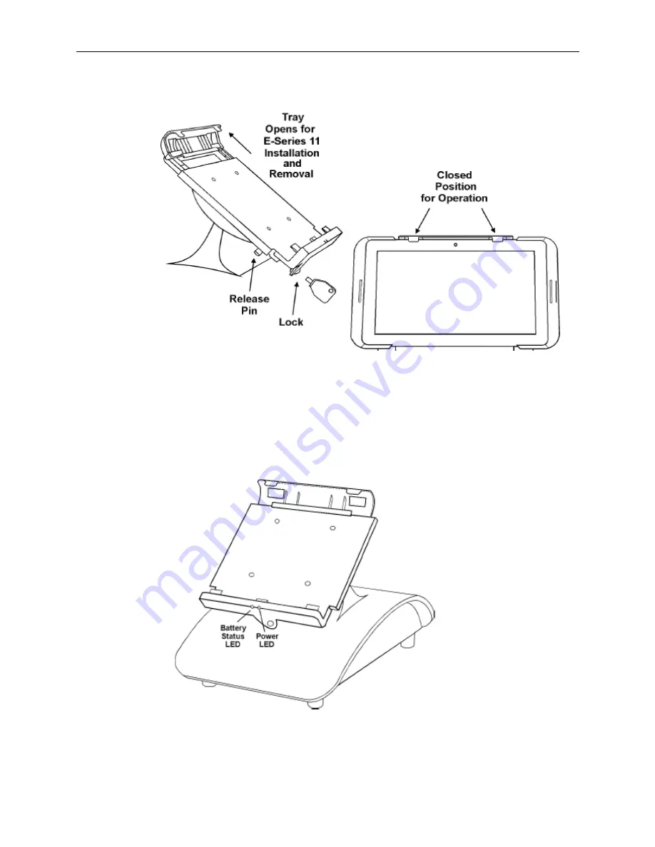
Figure 3-15 Base Station E-Series 11 Tray Retention Mechanism 

Details of the tray retention mechanism are shown above. The left side points out the 

location of the Release Pin that allows the tray to be lifted for installation and removal. 

After installation, the E-Series 11 tray can be secured using the provided One Way key. 
The Base Station E-Series includes two LEDs located at the base of the tray as shown in 

the Figure below. The Power LED displays Green when the E-Series 11 is installed. The 

Battery LED displays the charge and discharge status of the optional Smart Battery. 


Figure 3-16 Base Station E-Series Base Station LEDs 

Like the R-Series, the Base Station E-Series base does not include an AC power switch. 

When connected to AC Power, it remains in a low power sleep mode. 

Summary of Contents for e-series

Page 1: ...Oracle MICROS Tablet and Base Station E Series Setup Guide November 2015...

Page 2: ...rights are granted to the U S Government This software or hardware is developed for general use in a variety of information management applications It is not developed or intended for use in any inher...

Page 3: ...7 The Integrated Mini Printer 1 9 The Base Station E Series Wireless Scanner 1 10 Tablet E Series 11 General Specifications 1 11 Tablet E Series 8 General Specifications 1 12 Base Station E Series Gen...

Page 4: ...E Series USB Recovery Flash Drive 3 14 Using the Tablet E Series Recovery Controls 3 15 Windows Embedded 8 1 Industry Pro Lockdown Features 3 16 Basic Operation of the Base Station E Series 3 16 Inst...

Page 5: ...S Tablet and Base Station E Series LCD Customer Pole Display A 5 MICROS Tablet and Base Station E Series with Integrated Mini Printer A 6 MICROS Tablet and Base E Series with Integrated Scanner A 7 MI...

Page 6: ...eneral Specifications 1 13 Table 1 5 Base Station E Series Port Power Specifications 1 14 Table 1 6 Tablet E Series Safety and Environmental Certifications 1 15 Table 1 7 Base Station E Series Safety...

Page 7: ...lling the Base Station E Series Cover 2 9 Figure 3 1 Tablet E Series 8 Operator Controls 3 4 Figure 3 2 Tablet E Series 11 Operator Controls 3 5 Figure 3 3 Checking the MICROS Windows Embedded 8 1 Ima...

Page 8: ...Figure 3 24 Series 2 Integrated Customer Displays 3 23 Figure 3 25 Installing the Cable Guide 3 24 Figure 3 26 Installing the Integrated Mini Printer 3 25 Figure 3 27 Integrated Mini Printer Installa...

Page 9: ...r Support access My Oracle Support at the following URL https support oracle com When contacting Customer Support please provide the following Product version and program module name Functional and te...

Page 10: ......

Page 11: ...ng The Base Station E Series is derived from the Base Station R Series with a new Main Board as well as modifications to the docking tray and multi function connector Tablet E Series 8 The following f...

Page 12: ...eeve is also available with a 1D 2D scanner Optional MSR Sleeve The figure below shows details about the optional E Series 8 sleeve and USB Plug The USB Plug attaches to the E Series 8 Micro USB port...

Page 13: ...he Tablet E Series 11 ships with a Windows Embedded 8 1 Industrial Pro image customized to include the MICROS Client Application Loader CAL and the Tablet Base Station E Series Diagnostics Utility OS...

Page 14: ...Figure 1 5 Base Station E Series with the Tablet E Series 11 The Base Station E Series is AC powered and features an internal universal power supply In addition it can be equipped with an optional Tot...

Page 15: ...ray details are below Pulling the release pin allows the tray to be raised for installation or removal of the Tablet E Series 11 After installation the tray is closed and can be secured to Base Statio...

Page 16: ...Button releases the Base Station E Series tilt and rotate mechanism allowing you to change the orientation of the Tablet E Series 11 The figure below presents examples of portrait orientation with the...

Page 17: ...ntegrated and pole customer displays designed to match Base Station R Series and E Series styling Series 2 Integrated In the figure below the Series 2 2x20 Text LCD is on the left and the Series 2 240...

Page 18: ...240x64 and 2x20 Customer Displays Series 2 Pole The figure below shows front and side views of the Series 2 240x64 Pole Display Figure 1 11 Series 240x64 Pole Display The Series 2 pole and base are o...

Page 19: ...a Fujitsu thermal print mechanism and firmware and is not Epson compatible The printer is RS232 based and includes an interface cable with DB9F connector that is recommended for COM2 a powered RS232 P...

Page 20: ...ontains a Scan Engine and Image Decoder The Scan Engine is composed of a CCD imager lens motion sensor plus illumination and targeting LEDs housed in small a cube shaped package attached to the scanne...

Page 21: ...of 5 Korean 3 of 5 Inverse 1D GS1 DataBar Composite Codes Tablet E Series 11 General Specifications The Tablet E Series 11 with MSR sleeve specifications are listed below Table 1 2 Tablet E Series 11...

Page 22: ...ing Temperature 0 C 32 F to 40 C 104 F Weight 726g 1 7lb Dimensions Length 280mm 11 02 inches Width 177mm 6 97 inches Thickness 10 2 mm 0 40 inches Certifications http www dell com regulatory_complian...

Page 23: ...ure 0 C 32 F to 35 C 95 F Weight 400g 0 88lb Dimensions Length 216mm 8 51 inches Width 130mm 5 11 inches Thickness 9 mm 0 35 inches Certifications http www dell com regulatory_compliance_datasheets Ba...

Page 24: ...tery 3 08 kg 6 80lb Case Material PC ABS Plastic Physical Dimensions See Appendix A Base Station E Series Peripheral Power Specifications The Base Station E Series I O Panel includes two DB9 powered C...

Page 25: ...A is available at the COM1 connector for use with some small form factor printers A total of 13 5 Watts is available VCC5 4A is available at COM1 USB ports 1 through 5 and one or two customer displays...

Page 26: ...7 Base Station E Series Safety and Environmental Certifications Directive Specification Year Safety EN 60950 1 2006 A11 A1 A12 2011 2006 95 EC IEC 60950 1 2005 A1 2010 EMC EN 55022 2010 2010 2004 108...

Page 27: ...ain energized and present a shock hazard as long as the AC Power Cord is connected Always disconnect the AC power cord before opening the unit for service or configuration 1 Remove all cables from the...

Page 28: ...2 2 Identifying the Internal Components Figure 2 2 Removing the Base Station E Series Cover Figure 2 3 Base Station E Series Cables and Internal Components...

Page 29: ...tation E Series Main Board Description This section provides a block diagram of the Base Station E Series Main or System Board and describes the major components The block diagram is displayed below F...

Page 30: ...es MCU The Base Station E Series MCU is a NXP LPC1751 containing an ARM Cortex M3 Processor with 32kB Flash and 8kB SRAM on board The ARM Cortex M3 is a general purpose 32 bit microprocessor offering...

Page 31: ...wer supply voltages are off with the exception of a standby voltage As shown in the block diagram HEAD_DETECT is an input to the Base Station E Series from the Tablet E Series 11 HEAD_DETECT is forced...

Page 32: ...31 a USB to 2 Port Serial UART USB 3 0 Overview The USB 3 0 specification improves upon the USB 2 0 specification by adding a physically separate full duplex two ways communications channel on top of...

Page 33: ...d USB 2 0 Specification Each UART contains a large transmit and receive FIFO to optimize data throughput as detailed below Data rates up to 12 Mbps Fractional Baud Rates up to 12 Mbps 128 byte TX FIFO...

Page 34: ...eries with the battery The fuel gauge accurately predicts the battery capacity and other operational characteristics such as state of charge SOC time to empty TTE time to full TTF as well as an SOC in...

Page 35: ...nts 2 9 2 Reattach the cover and place the Base Station E Series face down to access the cover screws 3 Install the six security screws to fasten the Base Station E Series cover Figure 2 8 Installing...

Page 36: ......

Page 37: ...an anti static grade of carpeting is recommended If the carpeting surrounding the area housing the equipment is not composed of anti static material the use of static discharge mats is recommended Ant...

Page 38: ...Requirements AC Power Ethernet and MICROS IDN data cabling should be installed in accordance with the Oracle MICROS Hardware Site Preparation Guide Cleaning the Tablet Display Cabinet and Magnetic Str...

Page 39: ...tandard POS peripherals the Base Station E Series is also available Multi Bay Charger accessory future The E Series 8 is based on an Intel Atom Processor with 8 1 inch touch screen To add a Magnetic C...

Page 40: ...the Tablet and Base Station E Series Tablet E Series 8 Operator Controls The following illustrations point out the operator features of the Tablet E Series 8 with optional MSR Sleeve Figure 3 1 Tablet...

Page 41: ...and released turns the E Series 8 or E Series 11 On Off or enters exits sleep mode The E Series 11 Power Button behaves in the same manner when installed on the Base Station E Series When powering dow...

Page 42: ...s The Model is the Image Version and is located in the System section of the screen Figure 3 3 Checking the MICROS Windows Embedded 8 1 Image Version Turning the unit Off from the On state To turn off...

Page 43: ...6 point calibration utility can be found by starting Windows Explorer and navigate to the tabcal exe utility Tablet E Series 11 C Windows System32 tabcal exe Tablet E Series 8 C Windows System32 tabca...

Page 44: ...w and remove the tablet from the sleeve Figure 3 5 Removing the E Series 8 MSR Sleeve Installing the Tablet E Series 11 MSR Sleeve To install the Tablet E Series 11 into the optional MSR sleeve follow...

Page 45: ...leeve Removing the Tablet E Series 11 MSR Sleeve To remove the Tablet E Series 11 MSR sleeve follow the instructions below 1 Place the unit face down and turn the screws to the Unlock position 2 Remov...

Page 46: ...ssory charger and USB cable that can be used to charge the device when installed in the optional MSR Sleeve The E Series 11 includes a dual voltage charger 19 5V and 5V that is compatible with the E S...

Page 47: ...talling and Operating the Tablet and Base Station E Series 3 11 Figure 3 8 Charging the Tablet E Series 8 with the Accessory Charger Figure 3 9 Charging the Tablet E Series 11 with the Accessory Charg...

Page 48: ...ies 8 or Tablet E Series 11 device that will not boot to Windows Embedded 8 1 Industrial Pro 8 1 using the appropriate Tablet E Series USB Recovery Flash Drive The Tablet E Series USB Recovery Flash D...

Page 49: ...ange was requested to clear this computer s TPM Trusted Platform Module WARNING Clearing erases information stored on the TPM You will lose all created keys and access to data encrypted by those keys...

Page 50: ...es USB Recovery Flash Drive using a utility supplied with the recovery image The Tablet E Series 8 and E Series 11 each use a different hardware configuration and require unique images If supporting b...

Page 51: ...the Tablet E Series 8 and E Series 11 Power and Volume controls and where to attach the USB Recovery Flash Drive on each device The optional MSR Sleeve must be removed to use the USB Recovery Flash Dr...

Page 52: ...B Filter Allows only trusted USB devices to connect to the system Windows 8 Application Launcher Enables a single Windows Application to start automatically Currently the Windows Embedded 8 1 Industry...

Page 53: ...13 Front and Rear views of the Base Station E Series Base Pressing and holding the Rotate Button allows you to change the orientation as required The figure below shows an example of the adjustable tr...

Page 54: ...the E Series 11 tray can be secured using the provided One Way key The Base Station E Series includes two LEDs located at the base of the tray as shown in the Figure below The Power LED displays Gree...

Page 55: ...ng the Optional Base Station E Series Smart Battery The optional Base Station smart battery is an 11 1V 7200mAH Li Ion battery pack Totex DR202I The pack consists of nine rechargeable 18650 form facto...

Page 56: ...E Series 11 onto the Base Station Tray The Tablet E Series 11 can be docked on the Base Station tray in portrait or landscape mode 1 Position the tray in portrait or landscape orientation Figure 3 19...

Page 57: ...ions The optional Lithium Ion Smart Battery pack capacity will degrade over time The mechanisms for capacity loss do not require the battery to be charged or discharged a capacity decrease can also oc...

Page 58: ...e below shows the locations of the Integrated Customer Display Bracket the Wireless Scanner Dock and the Integrated Mini Printer on the Base Station E Series Figure 3 22 Base Station Peripheral Locati...

Page 59: ...ace cable and installation procedure Each display is compatible with both the Base Station R Series and Base Station E Series Figure 3 24 Series 2 Integrated Customer Displays The following procedure...

Page 60: ...stomer Display Installing the MICROS Integrated Mini Printer This section describes how to install the Integrated Mini Printer on the Base Station R Series or E Series The Integrated Mini Printer can...

Page 61: ...rating the Tablet and Base Station E Series 3 25 Figure 3 26 Installing the Integrated Mini Printer The figure below shows a typical Integrated Mini Printer installation Figure 3 27 Integrated Mini Pr...

Page 62: ...Controller with a UTP Modular connector The modular connector features an integrated isolation transformer as well as link and status indicator LEDs USB1 USB4 In addition to a MICROS powered USB port...

Page 63: ...rawer connectors are based on the 8 pin Mini DIN connectors Two of the additional pins are used to establish a serial interface between the Base Station and a future APG Smart Cash Drawer To support e...

Page 64: ......

Page 65: ...To minimize the Diagnostic Utility tap Hide 5 To exit the Diagnostic Utility tap Exit System Information This utility groups the Tablet s system and Base Station s battery information into one locatio...

Page 66: ...he total size includes all partitions BOOT Free Size Displays the remaining capacity of BOOT in bytes of the MMC Memory Device installed the Tablet BOOT contains the Tablet Platform files including th...

Page 67: ...Station to be connected to a Serial RS232 Roll Printer It opens an RS232 port on the Base Station and continuously transmits a sequence of print lines to the Output Port IDN Loopback This test requir...

Page 68: ...Electrical and mechanical tests effected by the door being open will change to red Scanner The Scanner test is used for the Base Station Wireless Scanner To use the scanner test the Scanner and Dock m...

Page 69: ...Appendix A A 1 Appendix A Equipment Dimensions This appendix includes dimensional drawings for the Oracle MICROS Tablet and Base Station E Series and peripheral equipment MICROS Tablet E Series 8...

Page 70: ...A 2 Appendix A MICROS Tablet E Series 11...

Page 71: ...Appendix A A 3 MICROS Tablet and Base Station E Series...

Page 72: ...A 4 Appendix A MICROS Tablet and Base Station E Series with Integrated LCD Customer Display...

Page 73: ...Appendix A A 5 MICROS Tablet and Base Station E Series LCD Customer Pole Display...

Page 74: ...A 6 Appendix A MICROS Tablet and Base Station E Series with Integrated Mini Printer...

Page 75: ...Appendix A A 7 MICROS Tablet and Base E Series with Integrated Scanner...

Page 76: ...A 8 Appendix A MICROS Tablet Multi Unit Charger Surface Mount...

Page 77: ...Appendix A A 9 MICROS Tablet Multi Unit Charger Wall Mount...

Page 78: ......

Page 79: ...S workstations Two configurations are detailed in the following pages configured through the POS application Warning Do not insert a 6 Pin modular plug into the 8 Pin IDN Port The 6 Pin plug can push...

Page 80: ...Appendix B IDN Port RS232 Peripheral The figure below shows the IDN port configured as a two wire RS232 interface RS232 COM 5 The Base Station includes one full featured modular COM port assigned to C...

Page 81: ...s port is targeted for use with the MICROS Integrated Mini Printer a compact thermal printer that receives power and data directly from the Base Station Cash Drawer 1 and 2 Connectors The figure below...

Page 82: ...B 4 Appendix B Pin Number Signal Name Description 3 7 8 Ground Signal Grounds 4 CD_ST Input Status from the Cash Drawer 5 MCU_TX_5V Tx data to Cash Drawer 6 MCU_RX Rx data from Cash Drawer...

Reviews: