background image

Manuel d'utilisation - User Manual

3. Controls and settings

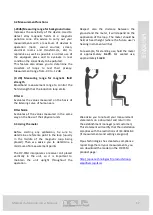
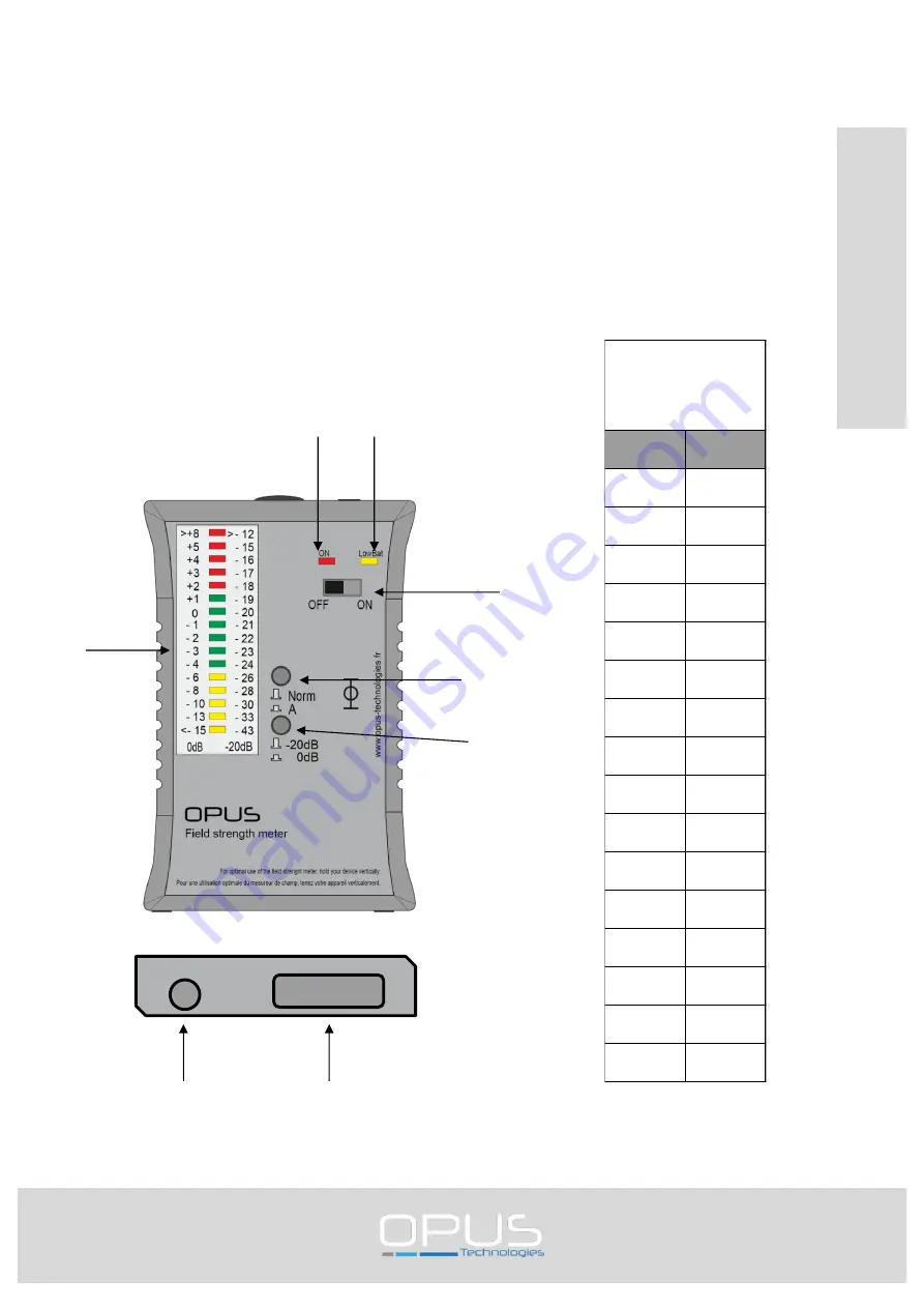
3.1 Overview of the connection jacks and operating elements

1. Color-coded display of the field strength

2. On/Off indicator

3. Battery-low indicator

4. On/Off switch

5. Filter selection switch

6. Measurement range selection switch

7. Headphone jack

8. Volume control for the headphones

16

EN

GL

IS

H


Switch setting for 

the measurement

range selection

switch (6)

0 dB

-20 dB

>+8

>-12

+5

-15

+4

-16

+3

-17

+2

-18

+1

-19

0

-20

-1

-21

-2

-22

-3

-23

-4

-24

-6

-26

-8

-28

-10

-30

-13

-33

<-15

-43

Phone

Volume

(2)

(3)

(1)

(4)

(5)

(6)

(7)

(8)

Summary of Contents for OP-FSM

Page 1: ...EN FR Manuel d installation et d utilisation OP FSM Installation and user manual OP FSM MESUREUR DE CHAMPS FIELD STRENGHT METER ...

Page 2: ...s 6 2 Description 7 2 1 La gamme 7 2 2 Le contenu 7 2 3 OP FSM 7 2 4 Conseils et sécurité 8 3 Commandes connexions et réglages 9 3 1 Synoptique des raccords et des éléments de commande 9 3 1 Fonctions de mesure 10 3 3 Déroulement des mesures 10 4 Guide pas à pas 11 5 Maintenance et entretien 12 6 Garantie 12 7 Caractéristiques techniques 13 TABLE DES MATIERES ...

Page 3: ...d notes 16 2 Description 16 2 1 The range 17 2 2 Contents 17 2 3 OP FSM 17 2 4 Safety notes 17 3 Connections and settings 18 3 1 Overview of the connection jacks and operating elements 18 3 2 Measurement functions 19 3 3 Using the meter 19 4 Step by step instructions 20 5 Maintenance and care 21 6 Warranty 21 7 Specifications 22 Table of contents ...

Page 4: ...Manuel d utilisation User Manual 4 FRANÇAIS FR Manuel d installation et d utilisation OP FSM ...

Page 5: ...alement la non observance d une alerte de type Remarque n entraîne pas de dommage matériel ou corporel Attention La non observance d une alerte de type attention peut entraîner des dommages matériels Avertissement La non observance d une alerte de type avertissement peut entraîner des dommages matériels et corporels graves Danger Le non respect d une alerte de danger peut entraîner la mort 1 4 Icô...

Page 6: ...us permet de bénéficier d une offre complète avec les outils nécessaire pour effectuer des installations conforme à la norme international IEC 60118 4 2 2 Le contenu Dès la réception du mesureur inspecter l appareil afin de contrôler les dommages qui auraient pu survenir pendant le transport Si le mesureur OP FSM est endommagée aviser votre distributeur et la société de transport immédiatement en ...

Page 7: ...Affichage marche arrêt 3 Indicateur de pile usée 4 Interrupteur marche arrêt 5 Sélecteur de filtre 6 Sélecteur de la plage de mesure 7 Raccord écouteur 8 Molette de réglage du volume pour les écouteurs 7 FRANÇAIS Phone Volume 2 3 1 4 5 6 7 8 Position du sélecteur de la plage de mesure 6 0 dB 20 dB 8 12 5 15 4 16 3 17 2 18 1 19 0 20 1 21 2 22 3 23 4 24 6 26 8 28 10 30 13 33 15 43 ...

Page 8: ... commencer tout calibrage prenez soin de déterminer un point de référence dans la boucle habituellement au milieu de la boucle magnétique posée Ensuite nous vous conseillons de déterminer un minimum de 6 points de mesures Le OP FSM intègre une bobine réceptrice placée verticalement dans l appareil il est donc important de maintenir l appareil à la verticale tout au long de l opération 8 FRANÇAIS R...

Page 9: ...s fr products loop amplifiers op fsm FRANÇAIS Mesure Signal nécessaire Sélecteurs de la plage de mesure et du filtre Point d alignement Valeurs de référence mesurées Étape 1 Position normale Amplificateur éteint OP FSM éteint OP FSM éteint Aucun Toutes les molettes de réglage en butée minimale Étape 2 Bruits de fond Amplificateur éteint 20dB A Plusieurs emplacements dans la boucle magnétique Maxim...

Page 10: ... des dommages occasionnés par une mauvaise manipulation ou si des personnes non autorisées ont tenté de réparer l appareil endommagement du cachet signalétique de l appareil Les réparations sous garantie ne sont exécutées qu après réception du coupon de garantie dûment rempli ou d une copie de la facture ou du ticket de caisse du revendeur Le numéro de l appareil doit être indiqué dans tous les ca...

Page 11: ...ctionnement 0dB 0dB 0 4A m Type de mesure True RMS 125ms Réponse en fréquences Filtre A Flat 30Hz 500Hz 3dB 4dB 500Hz 2500Hz 0 25dB 2500Hz 10KHz 3dB Sorties Écran LED de différentes couleurs Écouteurs Fiche de 3 5mm Alimentation électrique Piles 2xAA Contrôle LED Durée de service 100h Dimensions Dimensions L x H x P 83 x 126 x 35 mm Poids Environ 300g ...

Page 12: ...Manuel d utilisation User Manual 12 ...

Page 13: ...Manuel d utilisation User Manual 13 ENGLISH EN Installation and user manual OP FSM ...

Page 14: ... does not result in any material or bodily injury Attention Failure to observe a caution alert may result in property damage Warning Non compliance with a type alert Warning may result in serious personal injury and property damage Danger Failure to observe a danger alert may result in death 1 4 Icons 1 4 1 Icons and notes Icons used with notes provide additional information about it See the follo...

Page 15: ...anufacturing products allows you to benefit from a complete offer with the necessary tools to carry out installations in accordance with the international standard IEC 60118 4 2 2 The content Upon receipt of the meter inspect the unit for any damage that may have occurred during transport If it is damaged notify your distributor and the shipping company immediately indicating the delivery date the...

Page 16: ...n Off indicator 3 Battery low indicator 4 On Off switch 5 Filter selection switch 6 Measurement range selection switch 7 Headphone jack 8 Volume control for the headphones 16 ENGLISH Switch setting for the measurement range selection switch 6 0 dB 20 dB 8 12 5 15 4 16 3 17 2 18 1 19 0 20 1 21 2 22 3 23 4 24 6 26 8 28 10 30 13 33 15 43 Phone Volume 2 3 1 4 5 6 7 8 ...

Page 17: ...its 3 3 Using the meter Before starting any calibration be sure to determine a reference point in the loop usually in the middle of the magnetic loop being placed Then we advise you to determine a minimum of 6 measurement points The OP FSM incorporates a receiver coil placed vertically in the unit so it is important to maintain the unit upright throughout the operation Respect also the distance be...

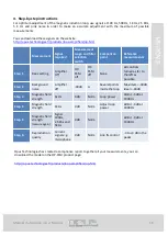
Page 18: ...tep 1 Basic setting Amplifier Off OP FSM off OP FSM off None All controls turned as far to the left as possible Step 2 Background noise Amplifier off 30dB A Several points inside the loop Maximum 30dB Ideal 43dB Step 3 Magnetic field strength 1kHz 0dB Norm Loop power 0dB 3dB at 1000Hz Step 4 Magnetic field strength 1KHz 0dB Norm Adjust loop power 0dB 3dB at 1000Hz Step 5 Magnetic field strength me...

Page 19: ...arranty does not apply for damage caused by mishandling or if unauthorized persons have attempted to repair the device damage to the device s stamp Warranty repairs are only performed after receipt of the completed warranty slip or a copy of the reseller invoice or receipt The number of the device must be indicated in all cases 7 Disposal Elimination of electrical and electronic equipment in Europ...

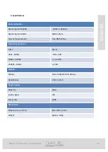
Page 20: ...0dB 0 4A m Type of measurement True RMS 125ms Frequency response Filter A Flat 30Hz 500Hz 3dB 4dB 500Hz 2500Hz 0 25dB 2500Hz 10KHz 3dB Outputs Display Color coded LED dot display Headphones 3 5mm cinch Power supply Batteries 2xAA Incator lights LED Service life 100h Dimensions Dimensions L x H x P 83 x 126 x 35 mm Weight Approx 300g ...

Page 21: ...Manuel d utilisation User Manual 21 ...

Page 22: ..._____________ _____________________________________________________ _____________________________________________________ _____________________________________________________ _____________________________________________________ _____________________________________________________ _____________________________________________________ _____________________________________________________ ________...

Page 23: ..._____________ _____________________________________________________ _____________________________________________________ _____________________________________________________ _____________________________________________________ _____________________________________________________ _____________________________________________________ _____________________________________________________ ________...

Page 24: ...ur toutes questions complémentaires contacter nous For any questions contact us OPUS TECHNOL OGIES ZI Lagrange II 9 Chemin de la Vieille Ferme 33650 MARTILLAC Tel 33 09 81 24 00 06 Fax 33 09 82 63 22 56 contact opus technologies fr 02 2018 ...

Reviews: