background image


optris LS – E2006-01-A 


Content 


Page 


Page 


Basic Operation   


Material and Location Names 


19 

Batteries  


  4 

Data Logger Recall 


20 

User interface 


  4 

Thermocouple 

Probe 

   21 

Display   


  5 

Software 

OptrisConnect 

   22 

Measurement 


Installation 

and 

Start 

   22 

Handling 


Connection 

to 

the 

Computer   22 

Measurement 

Functions 


Data 

Logger 

Functions 

   24 

Display Backlight   


  8 

Time Stamp 


25 

Laser Sighting 


  8 

Material and Location Names 


25


Optics   


  9 

Digital Displays   


26


Setup 

Menu 

    11 

Diagram Functions 


27 

Emissivity Setting  


11 

Device Setup 


32


High 

Alarm 

    12 

Device 

Information    33 

Low 

Alarm 

    12 

Specification 

    34


Long-Term 

Measurement 

(Lock 

Mode) 

 13 

Technical 

Data 

    34 

Setup 

Menu 

    14 

Factory 

Default 

Setting 

   36


Temperature 

Unit 

    14 

Troubleshooting 

    36 

Buzzer   


15 

Maintenance 


37 

Flip-Display 

    15 

Principle 

of 

Operation 

   38


Ambient Temperature Compensation 


16 

Emissivity 


39


Reset 


17 

Appendix A – Emissivity Table Metals 


41


Data Logger 


18 

Appendix B – Emissivity Table Non Metals   

42 

Storing Data


18


Summary of Contents for LaserSight

Page 1: ...optris LaserSight Operators manual...

Page 2: ......

Page 3: ...73 23 EEC Optris GmbH Str 49 Nr 14 D 13127 Berlin GERMANY Tel 49 30 500 197 0 Fax 49 30 500 197 10 E mail info optris de Internet www optris com Scope of Supply LS unit 2 batteries type AA t c inserti...

Page 4: ...The warranty period covers 24 months starting on the delivery date After the warranty is expired the manufacturer guarantees additional 6 months warranty for all repaired or substituted product compo...

Page 5: ...g 8 Material and Location Names 25 Optics 9 Digital Displays 26 Setup Menu 1 11 Diagram Functions 27 Emissivity Setting 11 Device Setup 32 High Alarm 12 Device Information 33 Low Alarm 12 Specificatio...

Page 6: ...close the cover lid Your new LaserSight is already equipped with batteries which are protected with a plastic strip against discharge during the transport please remove If the batteries are low the b...

Page 7: ...s information 1 Status information 2 Upper display Measurement functions MIN MAX DIF AVG indication Data logger position 3 Main display IR temperature and unit C F 4 Lower display HOLD emissivity prob...

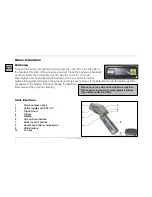
Page 8: ...used in vertical position measurement downwards With this handling small objects like electronic SMD components can easily be aimed and measured For this purpose please hold the unit as shown in the l...

Page 9: ...scaling will be done automatically between minimum reading no segment and maximum reading all segments Hold function The temperature will be displayed for 7 seconds after the Trigger is released The...

Page 10: ...e last measured value remains stored in the LS after switch off To recall this value please press in the switched off condition the I or II button The unit will be set into the HOLD mode In the emissi...

Page 11: ...actly marked with the patented crosshair laser i e the real size and location of the spot is shown on the object independently from the distance and with no optical offset see right figure In the CF m...

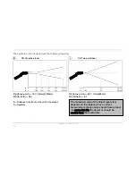
Page 12: ...16mm 1200mm D S focus point 62 1 1mm 62mm D S far field 36 1 D S far field 4 1 The measured area of the object spot size depends on the distance For a correct measurement the spot size should have at...

Page 13: ...rigger SAVE Measure mode I SAVE next menu item If none of these buttons is pressed the settings or changes done before will not be saved and the unit switches off after approx 30 s Emissivity Setting...

Page 14: ...C HOLD II I H flashes INCREASE VALUE V DECREASE VALUE II ACTIVATION DEACTIVATION alarm symbol beside H on off Low Alarm Setting of a temperature value alarm setpoint If the temperature reading is bel...

Page 15: ...l flashes ON OFF V ON OFF after setting to On 2x I HOLD Lock Trigger starting Measurement mode Lock or Trigger starting Measurement mode Lock You can deactivate the Lock function in the same order but...

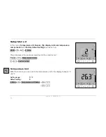
Page 16: ...settings can be set up HOLD II 4x I 2 Menu The procedure is the same as described in the setup menu 1 Trigger SAVE Measurement mode I SAVE next menu item Temperature Unit With this function you can s...

Page 17: ...n Off Default setting On 2 Menu II I Buzzer symbol flashes ON OFF V ON OFF Flip Display The LS has a so called Flip display turn around display As the unit can be used in horizontal and in vertical po...

Page 18: ...also the assignment of the Mode buttons I und II changes Ambient Temperature Compensation In dependence on the emissivity value a certain amount of ambient radiation will be reflected from the object...

Page 19: ...connected the lower display will toggle between Emissivity t c probe temperature and Tamb value Thermocouple Probe Reset With this function the unit can be set back to the factory default values Facto...

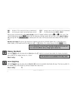
Page 20: ...and after this release the Trigger HOLD V Disc symbol next free Pos Pxx INCREASE POS NO V DECREASE POS NO I STORE1 HOLD 1 The storage will be confirmed with a double buzzer tone If you pull the Trigg...

Page 21: ...between 20 pre defined descriptions SURF ENG GLAS PVC etc To do this please start the data logger mode and choose a desired position Disc symbol choosen position Pxx II description flashes SURF GLAS P...

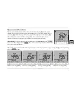
Page 22: ...d Disc symbol flashes P xx starting with position 00 To switch between the data logger positions and different displays please proceed as follows Upper display Main display Lower display Examples P 1...

Page 23: ...face You can connect the supplied insertion probe as well as any other t c probe type K To show the t c temperature in the display proceed as follows Trigger Toggle between T C probe temperature and E...

Page 24: ...wizard will start automatically Otherwise please start setup exe on the CD ROM Follow the instructions of the wizard until the installation is finished The installation wizard will place a launch icon...

Page 25: ...via the USB interface In this case operation is also possible if no batteries are inside the unit At digital communication the unit display shows the HOLD mode but the unit is measuring continuously a...

Page 26: ...ature TObj Min min object temperature TObj Max max object temperature TObj Avg average object temperature TObj Diff difference between TObj Min and TObj Max TInt internal unit temperature TExt t c tem...

Page 27: ...ime Stamp If you store data inside your LS for the first time after insertion of the batteries an internal timer will be started automatically When connected to a computer the timer will be synchroniz...

Page 28: ...cter the position number in the table appears red and the table cannot be closed with OK OK saves the changed table inside the LS Standard loads the standard table factory default in the connected uni...

Page 29: ...neath the display and pull it down The buttons of the tool bar will also be moved depending on the display size Diagram Functions STARTING THE MEASUREMENT To start a measurement please press the Start...

Page 30: ...range of the diagram will automatically be adapted to the respective peak values The range will remain as set during the whole measurement Control elements of the temperature axis 1 Global auto scali...

Page 31: ...query There is unsaved Data Save now Default setting activated Force data saving after stop if activated after each Stop an explorer window for saving the data will be opened automatically Decimal se...

Page 32: ...cel DIAGRAM SETTINGS The menu item Settings Menu Diagram Settings enables the selection of the following diagram options Digital Selection which signals should be displayed as digital display Diagram...

Page 33: ...ory Memory calculated from the max data count value will also be displayed in the status line Recording interval Time between single data 1ms 10s Recording time maximum time of measurement calculated...

Page 34: ...m this time the feature will appear in the Setup Menu 2 on the unit also if deactivated again in the device setup Ambient Temperature Compensation A reset of the unit to the factory default values Res...

Page 35: ...ill display the following unit specific information Device type Description from the manufacturer Firmware Rev Revision number of the internal software Hardware Rev Revision number of the internal har...

Page 36: ...chever is greater Accuracy t c input 0 75 C or 1 0 of reading whichever is greater Repeatability 0 5 C or 0 5 of reading whichever is greater Temperature coefficient 2 0 05K K or 0 05 K whichever is g...

Page 37: ...Power supply 2xAA Mignon Alkaline batteries or via USB cable if connected to a PC Battery life time 5h operating with laser and backlight 50 on 10h operating with laser and no backlight 25h operating...

Page 38: ...it back to these default values exception optics Troubleshooting Display Problem Action temperature reading LLLL object temperature below choose target within measurement range measuring range tempera...

Page 39: ...with the contact probe CAUTIONS Avoid static electricity arc welders and induction heaters Keep away from very strong EMF electromagnetic fields Don t leave the unit on or near objects of high temper...

Page 40: ...ate the surface temperature on the basis of the emitted infrared radiation from an object The most important feature of infrared thermometers is that they enable the user to measure objects contactles...

Page 41: ...accurate measuring results by interfering infrared radiation emitted by background objects flames heating systems chamottes To minimize measuring errors in such cases the handling should be performed...

Page 42: ...measured value corresponds to the temperature of the colored surface Characteristic Emissivities In case none of the methods mentioned above help to determine the emissivity you may use the emissivity...

Page 43: ...rolytic 0 05 0 15 roughened 0 05 0 1 oxidized 0 2 0 5 oxidized 0 4 0 8 Platinum black 0 9 Chrome 0 02 0 2 Silver 0 02 Gold 0 01 0 1 Steel polished plate 0 1 Haynes alloy 0 3 0 8 rustless 0 1 0 8 Incon...

Page 44: ...non oxidized 0 8 0 9 graphite 0 7 0 8 Carborundum 0 9 Ceramic 0 95 Concrete 0 95 Glass 0 85 Grit 0 95 Gypsum 0 8 0 95 Ice 0 98 Limestone 0 98 Paint non alkaline 0 9 0 95 Paper any color 0 95 Plastic...

Reviews: