background image

Delta Elec. Inc. 

DP-3638/DP-7606 


Company Confidential                    Optoma ______________________         Delta____________ 


26 

2010/01/04 

3. TROUBLE SHOOTING 

By checking operations during normal usage time, it is possible to carry out judgments on 

malfunction to a certain extent.   

Carry out the following checks before disassembling the equipment. 


Connect the power cord 

• Power Supply Unit malfunction


• Check the connection of Power Supply (Power BD 

CON201

 to MB 

P302

)

• Check keypad connection ( MB 

P801 

to Keypad

 CN101

• Check voltage (12v, 5v, 3.3v, 2.5v,1.8v,1.2v,…etc) on Main Board.


< Stand-by > 

Power: Amber Light 

Temp : OFF 
Lamp :OFF 


Yes

< Fan error > 

Power: Flashing Red 

Light6 

Temp: OFF 

Lamp: Flashing Red 

Light

1

2

3


• Check the system monitor & fan 
• Connector (

P8001

P8002

P8003

) on Main Board 

disconnected. 


< Power supply error > 

Power: OFF 

Temp: OFF 

Lamp: OFF


Yes

Yes


No


No


Summary of Contents for EW775

Page 1: ...Delta Elec Inc EX785_ EW775 Company Confidential Optoma___________________ Delta________________ 1 2010 01 05 DATA PROJECTOR EX785 DP 3638 EW775 DP 7606 SERVICE MANUAL...

Page 2: ...ntrol Parts 11 2 10 Adjusting Projected Image Position Using PureShift 13 2 11 PureShift Range Diagram 16 2 12 Adjusting Projection Image Size 17 2 13 BLOCK DIAGRAM 20 2 14 Explanation of Block Diagra...

Page 3: ..._ Delta________________ 3 2010 01 05 8 Projection Lamp 91 9 Cleaning 95 10 SERVICE NOTE 96 10 1 Service Note Description 96 10 2 Power READY LED Blink Code Message 97 10 3 Factory Preset Display Modes...

Page 4: ...repairs 3 Make sure that parts and screws and wiring etc are returned to their original positions Tube tape and other insulation materials have been used for safety reasons The internal wiring has be...

Page 5: ...back to the beam as much as possible 3 Ensure that projectors are located out of the line of sight from the screen to the audience this ensures that when presenters look at the audience they do not al...

Page 6: ...e 37 to 215 34 3 to 200 Throw ratio D W 1 6 2 1 62 2 03 Vertical keystone correction 30 degrees depend on input signal Projection methods Front Rear Desktop Front Rear Ceiling Data compatibility VGA S...

Page 7: ...el Spec Unit Min Max Typical Notes Color Segment RYGWB 55mm 2 4 Lamp Description Vendor OSRAM Type E20 9 330W Standard Mode 1500 Hours Standard 50 Survival Rate Lamp Life ECO Mode 2000 Hours Typical 5...

Page 8: ...R receive 11 Lens Cap 2 Top Cover 12 Power Button 3 Lens Release Button 13 LED Indicators 4 VerticaI and HorizontaI Lens 14 Input Output connections Shift Adjustment ControI 15 Back IR Receive 5 Contr...

Page 9: ...YPbPr 3 DVI D Connector 16 AUDIO IN L R RCA Video 4 VGA 2 YPbPr Connector 17 Video Connector 5 HDMI Connector 18 S Video Connector 6 USB Connector 19 YPbPr Connectors 7 RJ 45 Connector 20 BNC Connecto...

Page 10: ...Elec Inc DP 3638 DP 7606 Company Confidential Optoma ______________________ Delta____________ 10 2010 01 04 2 8 Control panel 1 Source Left 2 Keystone Up 3 Re Sync Right 4 Menu 5 Enter Help 6 Keystone...

Page 11: ...Sync 4 Freeze 5 Keystone 6 Page Up 7 Volume 8 Page Down 9 PC Mouse Control 10 Mouse Right Click 11 Enter Help 12 Four Directional Select Keys 13 Format 1 Number Button for password input 14 Source 4...

Page 12: ...the signal off certain reflective surfaces such as projector screens 3 The buttons and keys on the projector have the same functions as the corresponding buttons on the remote control This user s man...

Page 13: ...Delta Elec Inc DP 3638 DP 7606 Company Confidential Optoma ______________________ Delta____________ 13 2010 01 04 2 10 Adjusting Projected Image Position Using PureShift...

Page 14: ...110 and 10 for XGA 105 and 15 for WXGA of image height Note that the maximum vertical image height adjustment can be limited by the horizontal image position For example it is not possible to achieve...

Page 15: ...image position can be adjusted to the left or right by up to a maximum of 10 of the half image width Note that the maximum horizontal image height adjustment can be limited by the vertical image posi...

Page 16: ...Delta Elec Inc DP 3638 DP 7606 Company Confidential Optoma ______________________ Delta____________ 16 2010 01 04 2 11 Pure Shift Range Diagram EW775 WXGA EX785 XGA...

Page 17: ...elta Elec Inc DP 3638 DP 7606 Company Confidential Optoma ______________________ Delta____________ 17 2010 01 04 2 12 Adjusting Projection Image Size EX785 XGA STD lens offset 100 Long lens offset 100...

Page 18: ...Delta Elec Inc DP 3638 DP 7606 Company Confidential Optoma ______________________ Delta____________ 18 2010 01 04 Short lens offset 100 Adjusting Projection Image Size EW775 WXGA STD lens offset 100...

Page 19: ...Delta Elec Inc DP 3638 DP 7606 Company Confidential Optoma ______________________ Delta____________ 19 2010 01 04 Long lens offset 100 Short lens offset 100...

Page 20: ...Delta Elec Inc DP 3638 DP 7606 Company Confidential Optoma ______________________ Delta____________ 20 2010 01 04 2 13 Block Diagram Main Block...

Page 21: ...Delta Elec Inc DP 3638 DP 7606 Company Confidential Optoma ______________________ Delta____________ 21 2010 01 04 Block Diagram Left Block...

Page 22: ...Delta Elec Inc DP 3638 DP 7606 Company Confidential Optoma ______________________ Delta____________ 22 2010 01 04 Block Diagram Right Block...

Page 23: ...700 Digital input system DVI and HDMI The DVI and HDMI signals input to HDMI receiver U507 The signals are further converted into 10 bit digital signals of RGB YCbCr and then output to the scaler U700...

Page 24: ...e definition converter circuit ON screen display error diffusion circuit for DLP and output to the optical engine unit DLP DMD board Timing signal processing Scaler operates on an external single 32MH...

Page 25: ...______ Delta____________ 25 2010 01 04 Lamp power supply The lamp is lit with POWER ON Un lighting detection is performed Safety design Fan circuit detection Lamp cover detection Lamp house temperatur...

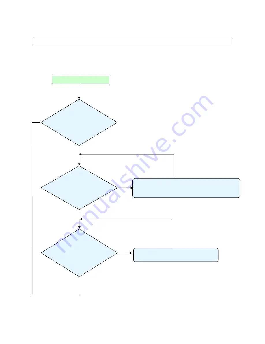
Page 26: ...the equipment Connect the power cord Power Supply Unit malfunction Check the connection of Power Supply Power BD CON201 to MB P302 Check keypad connection MB P801 to Keypad CN101 Check voltage 12v 5v...

Page 27: ...ng Power On DMD error Power Flashing Red Light 8 Temp OFF Lamp OFF Yes DMD chip error Check DMD Board PWB Ass y No Lamp Cover A ssy is not attached Connector P802 on Main Board disconnected or Thermal...

Page 28: ...in Board or Ballast Ass y malfunction Ignition sound exists Lamp failure Lamp is broken damaged or burst System Change a new Lamp Lamp error Power Flashing Red Light5 Temp OFF Lamp ON Normal operation...

Page 29: ...e occurs even after lamp replacement Press Menu key Remote controller set malfunction Low battery and outside operation rang Main Board Ass y malfunction Connector CN303 CN200 of IR PWB disconnected I...

Page 30: ...Are abnormalities noticeable on projection screen Does the lamp go off during operation System OK Normal operation Temperature protector operated due to the increase in temperature based on operating...

Page 31: ...t in suspending mode Ensure a connected notebook computer is configured for an external display This is usually done by pressing an Fn key combination on the notebook Image Problems Problem No image a...

Page 32: ...and Gamma settings on the Image menu of the OSD Lamp Problems Problem There is no light from the projector 1 Check that the power cable is securely connected 2 Ensure the power source is good by testi...

Page 33: ...any fluorescent lights in the room 4 Check the battery polarity 5 Replace the batteries 6 Turn off other Infrared enabled devices in the vicinity 7 Have the remote control serviced Audio Problems Prob...

Page 34: ...ptoma___________________ Delta________________ 34 2010 01 05 4 DISASSEMBLY AND ASSEMBLY Review and Remove the Lens Look the full set projector Look at the IO side Push the button and anti clockwise Re...

Page 35: ...ntial Optoma___________________ Delta________________ 35 2010 01 05 Remove the Lamp Cover and Lamp Module Remove the screws S01 Remove the Lamp cover Loose the screw Loose the screw D I S A S S E M B...

Page 36: ...l Optoma___________________ Delta________________ 36 2010 01 05 Remove the Lamp Module and Filter Look the Lamp 2 Look the Lamp 3 Look the Lamp 4 Remove Lamp filter D I S A S S E M B L Y Follow direct...

Page 37: ...___ Delta________________ 37 2010 01 05 Remove the Top Cover and Main Board shield Remove these seven long screws Look these seven screws S02 Take off the Top case Review the top area w o top case D I...

Page 38: ...________________ Delta________________ 38 2010 01 05 Remove the Main Board Review the shield Careful these grounding wires then you assembled Careful these connectors when you assembled Remove the thr...

Page 39: ...connector locations when you assembled again Careful the connector locations when you assembled again D I S A S S E M B L Y Careful the connector locations when you assembled again Careful the connect...

Page 40: ...W775 Company Confidential Optoma___________________ Delta________________ 40 2010 01 05 Main Board Review Careful these connector locations when you assembled again D I S A S S E M B L Y Main Board Re...

Page 41: ..._______ Delta________________ 41 2010 01 05 Remove the White Tube Remove the white long tube 1 Remove the white long tube 2 Remove the white long tube 3 Remove the white long tube 4 D I S A S S E M B...

Page 42: ..._______________ Delta________________ 42 2010 01 05 Remove the Front Cover Review the projector Remove the two screws S03 Remove the two screws Remove the two screws D I S A S S E M B L Y Review these...

Page 43: ..._______________ 43 2010 01 05 Remove Optical FAN and Optical Engine Review the Front Cover Review the projector Remove these 2 screws Review the Fan and the two screws S03 D I S A S S E M B L Y Remove...

Page 44: ...toma___________________ Delta________________ 44 2010 01 05 Remove the Optical Engine Remove the screw Remove the two screws Review the three screws S03 Review the Optical Engine 1 D I S A S S E M B L...

Page 45: ...___________________ Delta________________ 45 2010 01 05 Remove the Thermostat Color Wheel Look the optical engine 4 Look the optical engine 5 Remove these two screws S07 Remove the screw S07 D I S A S...

Page 46: ...ial Optoma___________________ Delta________________ 46 2010 01 05 Remove the Thermostat C W Look the Thermostat Remove these 3 screws S03 Look C W chassis Remove these 4 screws S03 D I S A S S E M B L...

Page 47: ...ma___________________ Delta________________ 47 2010 01 05 Remove the Index Board and IRIS Board Remove the screw S03 Look the Index Board Remove these 3 screws S09 Look the Optical Ring D I S A S S E...

Page 48: ...EW775 Company Confidential Optoma___________________ Delta________________ 48 2010 01 05 Remove the DMD Chip Remove the screw S11 Review the DMD Heat Sink Remove these 4 screws S11 Look the DMD Chip...

Page 49: ...___________ Delta________________ 49 2010 01 05 Remove the IO ASSY Review the projector Remove the three screws S03 Be careful the connector when you assembled Be careful the connector when you assemb...

Page 50: ...__________ Delta________________ 50 2010 01 05 Remove the IO Board Review the IO ASSY and remove the eight screws Remove the six screws Review the screws S04 S13 Review the IO BOARD D I S A S S E M B...

Page 51: ...ntial Optoma___________________ Delta________________ 51 2010 01 05 Remove the Ballast and FAN Remove the screw S03 Remove the screw S03 Remove the screw S03 Remove these 4 screws S03 D I S A S S E M...

Page 52: ...__________________ Delta________________ 52 2010 01 05 Removing the Fan and Power Board Take out off 4 black nuts Look the Fan 2 Remove these 4 screws S03 Look the Power Board D I S A S S E M B L Y Lo...

Page 53: ...__________ Delta________________ 53 2010 01 05 Remove Thermal Board and Lamp Module Chassis Look the Thermal Board Look the Lamp Module Chassis and Fan3 Remove these 2 screws S03 Remove the screw S03...

Page 54: ...__________ Delta________________ 54 2010 01 05 Remove Lamp Module Chassis and Fan 3 Remove the Lamp Module Chassis Look the Lamp Module Chassis and Fan3 Take out off 4 black nuts Look the Fan 3 D I S...

Page 55: ..._________________ Delta________________ 55 2010 01 05 Remove the ADJ Foot and Bottom Chassis Remove the screw S03 Remove the screw S03 Look the ADJ Foot Remove these 4 screws S03 D I S A S S E M B L Y...

Page 56: ...Delta Elec Inc EX785_ EW775 Company Confidential Optoma___________________ Delta________________ 56 2010 01 05 Review the Bottom Case Look the Bottom Case D I S A S S E M B L Y...

Page 57: ...5kg S02 M4 0 7 105 3105343500 5 6kg S03 M3 0 5 8 3100300800 4 5kg S04 HEX 4 7 4 3461431703 3 4kg S05 M3 6 3105280900 4 5kg S06 M2 0 5 3105130200 1 8 2 2kg S07 M3 0 5 10 3100301000 4 5kg S08 M2 4 3105...

Page 58: ...x y msi it will automatically launch the USB drivers update Following are the dialogues of the Driver Install process as below Step 1 This is the first page of install dialog Click on the Next button...

Page 59: ...ep 4 The Installer copies the necessary files to PC Step 5 Press the Finish button with the Launch checkbox checked the wizard will start the USB driver INF update Launch the driver update Note The US...

Page 60: ...ace it with the newer one Step 7 Remove the USB cable between PC and projector if it is connected The WinDrive USB drivers will be installed and registered to system Step 8 After the driver install a...

Page 61: ...mode Press Down Up Right Up key in sequence on keypad The power and lamp LED will blink and the Projector Control mode will be enabled Step 11 The New Hardware Wizard launched at the first time Window...

Page 62: ...driver is enumerated the projector information displayed in the status windows Click on the Check button to place the projector in the Flashtool mode The purpose of this function is to verify whether...

Page 63: ...tware automatically and Click on the Next button to continue In case the wizard cannot find the driver the ProjectorControl inf please select the other advanced option and specify the driver location...

Page 64: ...er the ProjectorControl inf please select the other advanced option and specify the driver location manually Normally at C Program Files Digital Zoom Projector Projector Flash Tool Step 22 Windows upd...

Page 65: ...VID_1501 Pid_3618xxx The DP3602 series VID_1501 Pid_3602xxx The DP3616 series VID_1501 Pid_3616xxx The DP3622 series VID_1501 Pid_3622xxx The PR301x series VID_1501 Pid_2617xxx The PR302x series VID_...

Page 66: ...e installed automatically via Windows USB hot plug mechanism 2 The Projector Control will be dynamically installed after entering the maintenance mode Hit key sequence as down up right up 3 The Projec...

Page 67: ...f Flash Tool are also included in the document System Requirement of Flash Tool 1 IBM compatible PC 2 Windows XP operating system English 3 Projector Flash tool USB driver installed New features of th...

Page 68: ...led yet please refer to the USB driver installation guide for further details Flash Tool User s Guide Upgrading Projector Firmware Step 1 Launch the FlashTool exe from installed short cut at Program D...

Page 69: ...under 1W stay Press Down Up Right Up keys in sequence using keypad buttons or using the IR remote controller for those with limited keypads The lamp LED will flashing RED one time and the Flash Tool m...

Page 70: ...e if the binary image is not a valid projector firmware Step 6 Press the Start button to update the flash with the chosen firmware A warning message box will appear for confirmation Press OK to contin...

Page 71: ...e Flash technology the old firmware will be erased first Therefore Flash Tool will automatically erase the old firmware before upgrading Step 9 After old firmware erased the new firmware upgrading pro...

Page 72: ...___________ Delta________________ 72 2010 01 05 Step 10 After the new firmware upgraded the Flash Tool will perform the final validation The dialog showed checksum with verification message Step 11 Co...

Page 73: ...of Flash Tool are also included in the document System Requirement of Flash Tool 4 IBM compatible PC 5 Windows XP operating system English 6 Projector Flash tool USB driver installed New features of...

Page 74: ...alled yet please refer to the USB driver installation guide for further details Flash Tool User s Guide Upgrading Projector Logo Step 1 Launch the FlashTool exe from installed short cut at Program Dig...

Page 75: ...ll flashing RED one time and please make sure the system is not under 1W stay Press Down Up Right Up keys in sequence using keypad buttons or using the IR remote controller for those with limited keyp...

Page 76: ...file which will be converted to RLE format and stored to the projector s flash memory The compressed RLE size cannot exceed the flash memory limitation otherwise try to reduce the colors by selecting...

Page 77: ...chance to stop the update Press OK button to start the firmware update Step 9 According to the Flash ROM technology Flash Tool needs to erase the old splash logo before adding the new one Step 10 Aft...

Page 78: ..._______________ Delta________________ 78 2010 01 05 Step 11 After the new logo is changed the Flash Tool will perform the final validation The dialog shows the checksum with a verification message Ste...

Page 79: ...then press the power button to turn on projector The Power LED will now flash blue The startup screen will display in approximately 30 seconds The first time you use the projector you can select your...

Page 80: ...s the button again to confirm the shut down If the button is not pressed the message will disappear in 15 seconds 2 The cooling fans continue to operate for about 10 seconds for cooling cycle and the...

Page 81: ...Days and hours that the projector can be used without entering the password Exiting to the Setup menu activates the Security Timer Once activated the projector requires a password on the specified dat...

Page 82: ...nge Password Use this submenu to change the security password for the projector 1 Select Change Password from the Security submenu 2 The Confirm Change Password dialog box displays 3 Select Yes 4 Ente...

Page 83: ...rity Setting Enable or disable the security password Enabled the current password is required to power on the projector and access the Security menu Disabled no password is required for any function W...

Page 84: ...tor signal properties Security Enter the signal menu Access the projector s security features Projector ID Select a two digit projector ID from 0 through 99 Audio Enter the Audio menu Set audio level...

Page 85: ..._____ 85 2010 01 05 6 Calibration Step of into Service Mode Step 1 To turn on the projector press the Remote controller to disappear the OSD then press Power key Left key Right key Down key Up key Ste...

Page 86: ...t pattern with White 240 240 240 and Black 16 16 16 for calibrate VGA Source After input ready press Enter key to calibration Input Pattern Step 2 After complete the OSD will show the picture as follo...

Page 87: ...select ADC Calibration YUV In this menu input pattern with 75 SMPTE pattern for calibrate YUV Source and notice that the input source must be 480i format After input ready press Enter key to proceed...

Page 88: ...ce Mode In the Service Mode C Switch bright mode and Pattern 47 16 Gray Scale and then check gray scales are still distinct D Select CW INDEX Delay Time The default value is 340 The range is 0 719 E S...

Page 89: ...tation Before removing or instaIIing the Iens be sure to turn off the projector wait untiI the cooing fans stop and turn off the main power switch Do not touch the Iens surface when removing or instal...

Page 90: ...__________ Delta________________ 90 2010 01 05 5 Pull out the existing Iens sIowIy Installing the New Lens 1 Align the notches and corrective position the electrical contact pad as shown in the pictur...

Page 91: ...gulations 2 Avoid touching the glass surface of the new lamp Doing so may shorten its operation life Warning Be sure to turn off and unplug the projector at least 60 minutes before replacing the lamp...

Page 92: ...ressing the Power button 2 Allow the projector to cool down at least 30 minutes 3 Disconnect the power cord 4 Unlock the lamp cover 5 Pull up and remove the cover 6 Use a screwdriver to remove the scr...

Page 93: ...screws meet the following specifications 1 Screw Type M4 2 Maximum screw length 11 mm 3 Minimum screw length 9 mm Refer to the following diagram to ceiling mount the projector Warning 1 If you buy cei...

Page 94: ...age Lamp Hour Display the cumulative lamp operating time Lamp Reminder Choose this function to show or to hide the warning message when the changing lamp message is displayed The message will appear u...

Page 95: ...Lightly wipe the lens in a circular motion Caution 1 Do not use abrasive cleaners or solvents 2 To prevent discoloration or fading avoid getting cleaner on the projector case 9 2 Cleaning the Case Ref...

Page 96: ...cause peeling of the color filter 3 Cleaning the DMD The DMD surface is glass and can be cleaned However avoid scratches as these can have a direct influence on the image In case of dust on the DMD su...

Page 97: ...or Messages POWER LAMP TEMP Error Code Message Blink Blink Static T1 temperature over temperature 0 0 ON Thermal Break 4 0 0 Lamp strike error 5 1 0 Ballast over temperature 5 2 0 Fan1 error Lamp Fan...

Page 98: ...Delta Elec Inc EX785_ EW775 Company Confidential Optoma___________________ Delta________________ 98 2010 01 05 10 3 Factory Preset Display Modes Computer Compatibility...

Page 99: ...Delta Elec Inc EX785_ EW775 Company Confidential Optoma___________________ Delta________________ 99 2010 01 05 Apple Mac Compatibility...

Page 100: ...Delta Elec Inc EX785_ EW775 Company Confidential Optoma___________________ Delta________________ 100 2010 01 05 11 RS 232 Command...

Page 101: ...Delta Elec Inc EX785_ EW775 Company Confidential Optoma___________________ Delta________________ 101 2010 01 05...

Page 102: ...Delta Elec Inc EX785_ EW775 Company Confidential Optoma___________________ Delta________________ 102 2010 01 05...

Page 103: ...Delta Elec Inc EX785_ EW775 Company Confidential Optoma___________________ Delta________________ 103 2010 01 05...

Page 104: ...Delta Elec Inc EX785_ EW775 Company Confidential Optoma___________________ Delta________________ 104 2010 01 05...

Page 105: ...Delta Elec Inc EX785_ EW775 Company Confidential Optoma___________________ Delta________________ 105 2010 01 05...

Page 106: ...Delta Elec Inc EX785_ EW775 Company Confidential Optoma___________________ Delta________________ 106 2010 01 05...

Page 107: ...Delta Elec Inc EX785_ EW775 Company Confidential Optoma___________________ Delta________________ 107 2010 01 05 RS232 Connect Diagram RS232 CABLE 1 2 3 4 5 7 8 9...

Page 108: ...Hex 16 Week of Manufacture _________________ 1 17 Year of Manufacture _________________ 2009 18 EDID Version Number _________________ 1 19 EDID Revision Number ________________ 3 20 VIDEO INPUT DEFINI...

Page 109: ...Hz VESA 800 X 600 56Hz VESA 800 X 600 60Hz VESA 36 ESTABLISHED TIMING II 800 X 600 72Hz VESA 800 X 600 75Hz VESA 832 X 624 75Hz Apple Mac II 1024 X 768 60Hz VESA 1024 X 768 70Hz VESA 1024 X 768 75Hz V...

Page 110: ...2 89 Detailed Timing Descriptor Block 2 1280 X 720 Pixel Clock 130 MHz Horizontal Image Size 0 mm Vertical Image Size 0 mm Refreshed Mode Non Interlaced Horizontal Active Time 1280 pixels Blanking Tim...

Page 111: ...____________________ 1 13H EDID Revision Number _________________________ 3 14H VIDEO INPUT DEFINITION Digital Signal 15H Maximum Horizontal Image Size ________________ mm 16H Maximum Vertical Image S...

Page 112: ...1024 85Hz Standard Timing ID 6 1400 x 1050 60Hz Standard Timing ID 7 1600 x 1200 60Hz Standard Timing ID 8 1920 x 1080 60Hz ______________________________________________________________________ 36H...

Page 113: ...8 pixels Sync Pulse Width 32 pixels Border 0 pixels Frequency 90 28 kHz Vertical Active Count 720 lines Blanking Count 30 lines Sync Offset 5 lines Sync Pulse Width 5 lines Border 0 lines Frequency 12...

Page 114: ...9 94 60Hz 4 3 07H 720 x 480 P 59 94 60Hz 16 9 08H 720 x 576 P 50Hz 4 3 09H 720 x 576 P 50Hz 16 9 0AH 1280 x 720 P 59 94 60Hz 16 9 Native Mode 0BH 1920 x 1080 I 59 94 60Hz 16 9 0CH 1280 x 720 P 50Hz 16...

Page 115: ...1 47 kHz Vertical Active Count 480 lines Blanking Count 45 lines Sync Offset 9 lines Sync Pulse Width 6 lines Border 0 lines Frequency 59 94 Hz Digital Separate Horizontal Polarity Vertical Polarity 3...

Page 116: ...Width 5 lines Border 0 lines Frequency 60 00 Hz Digital Separate Horizontal Polarity Vertical Polarity 56H 68H Detailed Timing Descriptions 1280x720 Pixel Clock 74 25 MHz ____________________________...

Page 117: ...Week of Manufacture _________________ 1 17 Year of Manufacture _________________ 2009 18 EDID Version Number _________________ 1 19 EDID Revision Number ________________ 3 20 VIDEO INPUT DEFINITION An...

Page 118: ...Hz VESA 800 X 600 56Hz VESA 800 X 600 60Hz VESA 36 ESTABLISHED TIMING II 800 X 600 72Hz VESA 800 X 600 75Hz VESA 832 X 624 75Hz Apple Mac II 1024 X 768 60Hz VESA 1024 X 768 70Hz VESA 1024 X 768 75Hz V...

Page 119: ...2 89 Detailed Timing Descriptor Block 2 1280 X 720 Pixel Clock 130 MHz Horizontal Image Size 0 mm Vertical Image Size 0 mm Refreshed Mode Non Interlaced Horizontal Active Time 1280 pixels Blanking Tim...

Page 120: ...__________________ 1 13H EDID Revision Number _________________________ 3 14H VIDEO INPUT DEFINITION Digital Signal 15H Maximum Horizontal Image Size ________________ mm 16H Maximum Vertical Image Siz...

Page 121: ...1024 85Hz Standard Timing ID 6 1400 x 1050 60Hz Standard Timing ID 7 1600 x 1200 60Hz Standard Timing ID 8 1920 x 1080 60Hz ______________________________________________________________________ 36H...

Page 122: ...8 pixels Sync Pulse Width 32 pixels Border 0 pixels Frequency 90 28 kHz Vertical Active Count 720 lines Blanking Count 30 lines Sync Offset 5 lines Sync Pulse Width 5 lines Border 0 lines Frequency 12...

Page 123: ...6H 720 x 480 P 59 94 60Hz 4 3 07H 720 x 480 P 59 94 60Hz 16 9 08H 720 x 576 P 50Hz 4 3 09H 720 x 576 P 50Hz 16 9 0AH 1280 x 720 P 59 94 60Hz 16 9 Native Mode 0BH 1920 x 1080 I 59 94 60Hz 16 9 0CH 1280...

Page 124: ...xels Border 0 pixels Frequency 31 47 kHz Vertical Active Count 480 lines Blanking Count 45 lines Sync Offset 9 lines Sync Pulse Width 6 lines Border 0 lines Frequency 59 94 Hz Digital Separate Horizon...

Page 125: ...ines Sync Pulse Width 5 lines Border 0 lines Frequency 60 00 Hz Digital Separate Horizontal Polarity Vertical Polarity 56H 68H Detailed Timing Descriptions 1280x720 Pixel Clock 74 25 MHz _____________...

Page 126: ...projector provides additional diverse networking and remote management features The LAN RJ45 function of the projector through a network such as remotely manage Power On Off brightness Contrast settin...

Page 127: ...______ Delta________________ 127 2010 01 05 13 2 On the PC Laptop select Start Control Panel Network connections 13 3 Right Click on your Local Area Connection and select Property 13 4 In the Properti...

Page 128: ...128 2010 01 05 13 5 Click Properties 13 6 Fill in the IP address and Subnet mask then press OK 13 7 Press the Menu button on the projector 13 8 Select OSD SETUP Network Enabled DHCP OFF 13 9 Input th...

Page 129: ...01 05 13 10 Press Apply Enter to confirm settings 13 11 Open a web browser ex Microsoft Internet Explorer with Adobe Flash Player 9 0 or high 13 12 In the Address bar input the IP address 10 10 10 10...

Page 130: ...FOOT 3390704100 V V 1 ADJ FOOT 10 FOOT RUB 18 14 5 BLK 3245059600 V V 1 Fan1 11 DC FAN ASSY BFB0612H SE03 L110 50 60 B 3620640411 V V 1 Fan3 12 DC FAN ASSY NFB10512HF SE00 L85 25 105 B 3620101011 V V...

Page 131: ...V 1 Thermal 30 WIRE WITH THERMISTOR 3791106800 V V 1 31 END BLOCK EPE 600 500 160 WHT 3501506601 V V 1 Block 32 END BLOCK EPE 600 500 198 WHT 3501506700 V V 1 BAG PE 33 BAG PE 450 530 3500957300 V V 1...

Page 132: ...Delta Elec Inc EX785_ EW775 Company Confidential Optoma___________________ Delta________________ 132 2010 01 05 1 2 3 4 5 6 7 8 9 10 11 12 13 14 15 16 17 18 19 20 21 22 23 24 25...

Page 133: ...Delta Elec Inc EX785_ EW775 Company Confidential Optoma___________________ Delta________________ 133 2010 01 05 26 27 28 29 30 31 32 33 34 35 36 37 38 39 40...

Reviews: