Version 1.0.1 - 2021-07-06
111
Originalbetriebsanleitung
DH 40CT - 3034349
DE | EN
D
H
4
0
CT-3034
349_
part
s
.f
m
F
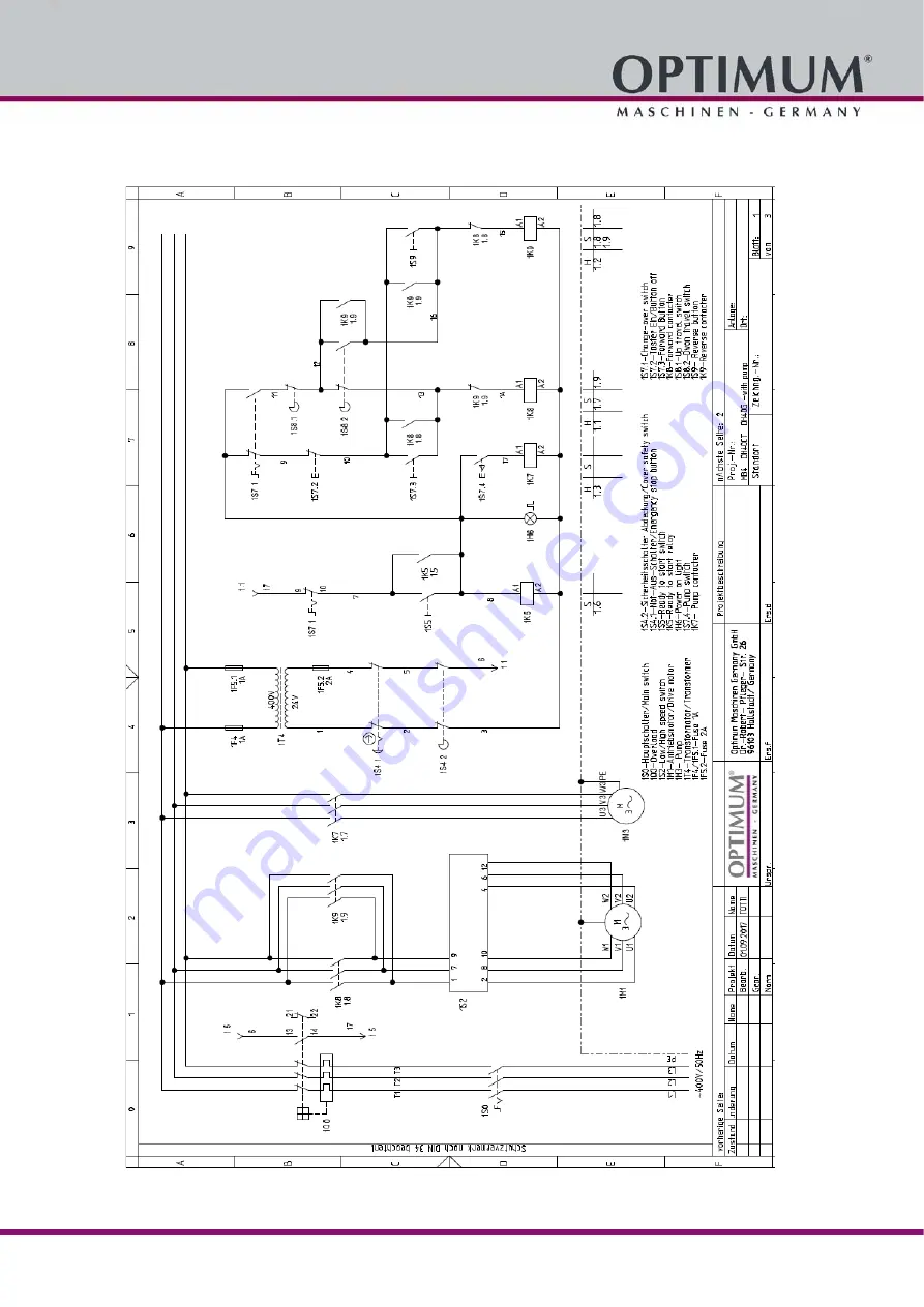
Schaltplan mit Kühlmitteleinrichtung - Wiring diagram with coolant device
Page 1: ...Betriebsanleitung DE Operating manual EN Version 1 0 1 Getriebe Bohr Fr smaschine Gearbox drilling milling machine Artikel Nr Part no 3034349...
Page 2: ...herheits berpr fung 16 1 11 K rperschutzmittel 16 1 12 Sicherheit w hrend des Betriebs 17 1 13 Sicherheit bei der Instandhaltung 17 1 13 1 Abschalten und Sichern der Bohr Fr smaschine 18 1 14 Verwende...
Page 3: ...3 Spindelkopf heben und senken 33 4 10 Werzeugaufnahmen 33 4 10 1 Einbau Bohrfutter 33 4 10 2 Ausbau Bohrfutter 33 4 10 3 Einbau Fr swerkzeuge 34 4 10 4 Ausbau Fr swerkzeuge 34 4 10 5 Verwendung von S...
Page 4: ...onably foreseeable misuse 58 1 4 1 Avoidance of misapplication 58 1 5 Possible dangers caused by the drilling milling machine 58 1 6 Qualification of personnel 59 1 6 1 Target group 59 1 6 2 Authorize...
Page 5: ...the machine 75 4 3 1 Switching off the machine 75 4 4 Feed for milling 75 4 5 Speed setting 75 4 5 1 Selecting the speed 75 4 5 2 Gear selector switch 76 4 6 Switching off the drilling milling machin...
Page 6: ...ts 92 7 Malfunctions 8 Appendix 8 1 Copyright 95 8 2 Terminology Glossary 95 8 3 Storage 95 8 4 Liability claims warranty 96 8 5 Advice for disposal Options of reuse 96 8 5 1 Decommissioning 97 8 5 2...
Page 7: ...r Lebensdauer Im Abschnitt Wartung sind alle Wartungsarbeiten und Funktionspr fungen beschrieben die vom Benutzer regelm ig durchgef hrt werden m ssen Die im vorliegenden Handbuch vorhandenen Abbildun...
Page 8: ...n stets in der N he der Bohr Fr smaschine auf INFORMATION K nnen Sie Probleme nicht mit Hilfe dieser Betriebsanleitung l sen fragen Sie an bei Optimum Maschinen Germany GmbH Dr Robert Pfleger Str 26 D...
Page 9: ...k nnte zu einer ernsten Verletzung von Personen oder zum Tode f hren VORSICHT Gef hrlichkeit oder unsichere Verfahrensweise die zu einer Verletzung von Personen oder einem Eigentumsschaden f hren k nn...
Page 10: ...ehmen keine Haftung f r Sch den aufgrund einer nicht bestimmungsgem en Ver wendung Wir weisen ausdr cklich darauf hin dass durch nicht von der Firma Optimum Maschinen Ger many GmbH genehmigte konstruk...
Page 11: ...n Maschinentisch gespannt ist Einsatz von K hl und Schmiermittel zur Steigerung der Standzeit am Werkzeug und Ver besserung der Oberfl chenqualit t Spannen der Bearbeitungswerkzeuge und Werkst cke auf...
Page 12: ...mit den vorgeschriebenen Sicherheitseinrichtungen ausger stet sein Sie als Betreiber sind daf r verantwortlich Sicherheitseinrichtungen auf Seite 14 1 6 Qualifikation des Personals 1 6 1 Zielgruppe D...
Page 13: ...schulten Fachkr fte des Betreibers und des Herstellers Der Betreiber muss Pflichten des Betreibers das Personal schulen das Personal in regelm igen Abst nden mindestens einmal j hrlich unterweisen ber...
Page 14: ...che Vorsichtsma nahmen treffen um eine Gesundheitsgef hrdung sicher abzuwenden 1 9 Sicherheitseinrichtungen Betreiben Sie die Bohr Fr smaschine nur mit ordnungsgem funktionierenden Sicherheits einrich...
Page 15: ...ter kann in der Stellung 0 durch ein Vorh ngeschloss gegen unbefugtes oder versehentliches Einschalten gesichert werden Bei ausgeschaltetem Hauptschalter ist die Stromzufuhr zu den Motoren unterbroche...
Page 16: ...arkierungen auf der Bohr Fr smaschine lesbar sind evtl reinigen vollst ndig sind INFORMATION Benutzen Sie die nachfolgende bersicht um die Pr fungen zu organisieren 1 11 K rperschutzmittel Bei bestimm...
Page 17: ...n WARNUNG Vor dem Einschalten der Bohr Fr smaschine berzeugen Sie sich davon dass da durch keine Gefahr f r Personen entsteht keine Sachen besch digt werden Unterlassen Sie jede sicherheitsbedenkliche...
Page 18: ...n Schutz und Sicherheitseinrichtungen wie Abdeckungen Sicherheitshinweise und Warnschilder Erdungskabel Wenn Sie Schutz oder Sicherheitseinrichtungen entfernen dann bringen Sie diese unmittelbar nach...
Page 19: ...iebsmittel den Bestimmungen der Unfallverh tungsvorschrift entsprechend beschaffen sind siehe Konformi t tserkl rung Ortsfeste elektrische Anlagen und Betriebsmittel gelten als st ndig berwacht wenn s...
Page 20: ...1 1 1 5 kW Bohrleistung in Stahl mm 32 Dauerbohrleistung in Stahl mm 28 Messerkopfgr e max mm 76 Schaftfr sergr e max mm 25 2 3 Spindelkopf Pinolenhub Spindel mm 120 Spindelaufnahme MK4 Spindelkopf 36...
Page 21: ...eners Charakteristika des Arbeitsraumes z B Gr e oder D mpfungsverhalten anderen Ger uschquellen z B die Anzahl der Maschinen andere in der N he ablaufenden Prozesse und die Zeitdauer w hrend der ein...
Page 22: ...Technische Daten Version 1 0 1 2021 07 06 22 Originalbetriebsanleitung DH 40CT DE DH40CT_DE_2 fm 2 12 Stellplan DH 40CT Abb 2 1 Abmessungen DH40CT mit Maschinenfu ohne K hlmitteleinrichtung 605 405...
Page 23: ...ttel die unter Last rei en Pr fen Sie die Hebezeuge und Lastanschlagmittel auf ausreichende Tragf higkeit und einwandfreien Zustand Beachten Sie die Unfallverh tungsvorschriften der f r Ihre Firma zus...
Page 24: ...kontrollieren Sie ob das gesamte Mate rial wie Verladepapiere Anleitungen und Zubeh rteile mit der Maschine geliefert wurden 3 3 Lieferumfang Einige der unten dargestellten Bauteile k nnen auch bereit...
Page 25: ...leuchtungsst rke von 500 Lux erreicht wird Falls dies mit der herk mmlichen Ausleuchtung des Aufstellungsorts nicht gew hrleistet ist muss eine zus tzliche Arbeitsplatzleuchte eingesetzt werden 3 4 5...
Page 26: ...iken jedes anderen ltyps Ihrer Wahl herangezogen werden 3 6 Erste Inbetriebnahme ACHTUNG Vor Inbetriebnahme der Maschine sind alle Schrauben Befestigungen bzw Sicherungen zu pr fen und ggf nachzuziehe...
Page 27: ...iterium bei der Auswahl Ihres K hlschmiermittels und der Reinigung der Maschine Ein Einkomponentenlack mit L semittelanteil h rtet aus indem sich das L semittel verfl chtigt Sobald der Lack aufgetrage...
Page 28: ...gesetzt Die Betriebsanleitung wird beachtet Alle Sicherheitseinrichtungen sind vorhanden und aktiv Beseitigen Sie oder lassen Sie St rungen umgehend beseitigen Setzen Sie die Maschine bei Funktionsst...
Page 29: ...en Kr fte beim Gleichlauf und Gegenlauffr sen auf die Spindeln des Kreuztisches Die Schnittkr fte beim Gleichlauffr sen tendieren dazu dass sich das Werkzeug in das Material hineinzieht Das Gegenlauff...
Page 30: ...riebenen Nachschlage und Tabellenwerken schlie en 4 5 2 Getriebewahlschalter Mit den Getriebewahlschaltern wird eine Geschwindigkeitsauswahl vorgenommen In Verbindung mit den Geschwindigkeitsstufen am...
Page 31: ...l st sein bevor Sie den Pinolenhebel verwenden k nnen Die Bet tigung des Pinolenhebels mit aktiviertem Feinvorschub kann die Kupplung besch digen L sen Sie die R ndelschraube gegen den Uhrzeigersinn D...
Page 32: ...riebe l an der Bel ftungs ffnung austreten Abb 4 5 Klemmschraube Spindelkopf VORSICHT Werden die Schrauben vollst ndig herausgedreht kann es zum Herabst rzen des Spindelkopfes kommen Beim Schwenken de...
Page 33: ...rs ist die Anzugsstange aus der Spindel zu entfernen wenn das Bohrfutter nicht mit der Anzugsstange befestigt werden kann Das Bohrfutter wird durch eine formschl ssige Verbindung Mitnehmer gegen Verdr...
Page 34: ...iter damit das Werkzeug aus der Kegelaufnahme herausge dr ckt wird ACHTUNG Beim Einbau eines kalten Morsekonus in eine warme Maschine neigen diese MK Aufnahmen im Vergleich zu Steilkegelaufnahmen dazu...
Page 35: ...muss immer in einem Maschinenschraubstock Backenfutter oder mit anderen geeigneten Spannwerkzeugen wie z B Niederhalter Spannpratzen auf dem Kreuztisch befestigt werden 4 13 1 Berechnung der Schnittk...
Page 36: ...orgung der verwendeten K hl und Schmiermittel Beachten Sie die Entsorgungshinweise der Hersteller 4 15 F r Maschinen mit K hlmitteleinrichtung Stellen Sie die Durchflussmenge mit dem Absperr und Dosie...
Page 37: ...Legierung spr de 60 100 0 10 0 15 0 30 0 40 0 60 CuZn Legierung z h 35 60 0 05 0 10 0 25 0 35 0 55 Aluminium Legierung bis 11 Si 30 50 0 10 0 20 0 30 0 40 0 60 Thermoplaste 20 40 0 05 0 10 0 20 0 30 0...
Page 38: ...98 498 597 697 796 995 1194 1592 1990 17 0 75 112 150 187 225 281 337 375 468 562 656 749 937 1124 1499 1873 18 0 71 106 142 177 212 265 318 354 442 531 619 708 885 1062 1415 1769 19 0 67 101 134 168...
Page 39: ...ndern quetscht das Material Die Querschneide hat zu den Haupt schneiden einen Winkel von 55 Als allgemeine Faustregel gilt Der Vorbohrdurchmesser richtet sich nach der L nge der Querschneide Empfohlen...
Page 40: ...eten labsorptionsmitteln und entsorgen Sie diese nach den geltenden Umweltschutz Vorschriften Auffangen von Leckagen Geben Sie Fl ssigkeiten die bei der Instandsetzung oder durch Leckagen au erhalb de...
Page 41: ...cht besch digt wird 6 2 Inspektion und Wartung Die Art und der Grad des Verschlei es h ngt in hohem Ma e von den individuellen Einsatz und Betriebsbedingungen ab Alle angegebenen Intervalle gelten des...
Page 42: ...ssen des les wieder mit Getriebe l Achten Sie auf den richtigen F ll stand Betriebsmittel auf Seite 21 monatlich Klemmschrauben Spindelkopf fest angezogen Pr fen Sie ob die Klemmschrauben zum Schwenke...
Page 43: ...notwendige Spiel der beiden Verzahnungen von H lse und Spindel Das im Auslieferungszu stand dort befindliche Fett ist m glicherweise verbraucht Abb 6 4 Das Nachfetten erfolgt von oben ber den Antrieb...
Page 44: ...hinen GmbH Dr Robert Pfleger Str 26 96103 Hallstadt einen Kundendiensttechniker stellen jedoch kann die Anforderung des Kundendiensttechnikers nur ber Ihren Fachh ndler erfolgen F hrt Ihr qualifiziert...
Page 45: ...immendes l oder Erh hung der Bakterienzahl auf ber 10 6 ml einem Anstieg des Gehaltes von Nitrit auf ber 20 ppm mg 1 oder Nitrat auf ber 50 ppm mg 1 einem Anstieg des Gehaltes an N Nitrosodiethanolami...
Page 46: ...ssbereich w chentlich 1 bei pH Wert Abfall 0 5 bez glich Erstbef llung Ma nahmen gem Herstellerempfehlung 1 0 bez glich Erstbef llung KSS austauschen KSS Kreislauf reinigen Gebrauchskonzentration Hand...
Page 47: ...Bohrer nicht richtig eingespannt Bohrfutter defekt Ersetzen Sie den Bohrer Lassen Sie die Lager am Spindelkopf austauschen Spannen Sie den Bohrer richtig Tauschen Sie das Sie das Bohrfutter aus Das B...
Page 48: ...ck ist nicht befestigt Lagerluft nachstellen oder Lager austauschen Lagerluft nachstellen Festlager Leiste mit Nachstellschraube auf richtiges Spiel einstellen Kontrollieren Nachziehen Werkzeug sch r...
Page 49: ...oder bereits ausgepackten Teile nur unter den vorgesehenen Umgebungsbedingungen Beachten Sie die Anweisungen und Angaben auf der Transportkiste Begriff Erkl rung Bohrpinole Feststehende Hohlwelle in d...
Page 50: ...keiten und der bestimmungs gem en Verwendung insbesondere bei berbeanspruchung des Ger tes Selbstverschulden durch Fehlbedienung bzw Missachtung unserer Betriebsanleitung nachl ssige oder unrichtige B...
Page 51: ...k nnen nach Aufarbeitung wiederverwendet werden wenn Sie an eine Wertstoffsammelstelle oder an das f r Sie zust ndige Entsorgungsunternehmen weitergegeben werden Geben Sie das Verpackungsmaterial nur...
Page 52: ...diese Ger te Das Symbol auf dem Produkt oder seiner Verpackung weist darauf hin dass dieses Produkt nicht als normaler Haushaltsabfall zu behandeln ist sondern an einer Annahmestelle f r das Recycling...
Page 53: ...wandt EMV Richtlinie 2014 30 EU Beschr nkung der Verwendung bestimmter gef hrlicher Stoffe in Elektro und Elektronikger ten 2015 863 EU Die Schutzziele der EG Richtlinie 2006 42 EG werden eingehalten...
Page 54: ...intenance all maintenance works and functional tests are described which the operator must perform in regular intervals The illustration and information included in the present manual can possibly dev...
Page 55: ...he drilling milling machine INFORMATION If you are unable to rectify an issue using these operating instructions please contact us for advice Optimum Maschinen Germany GmbH Dr Robert Pfleger Str 26 D...
Page 56: ...y or death CAUTION A danger or unsafe procedure that can cause personal injury or damage to property ATTENTION Situation that could cause damage to the drilling milling machine and prod uct as well as...
Page 57: ...ing milling machine is being used improperly We will not be held liable for any damages resulting from any operation which is not in accord ance with the intended use We expressly point out that the g...
Page 58: ...tool and to improve the surface quality Clamp the cutting tools and workpieces on clean clamping surfaces Sufficiently lubricate the machine Set the bearing clearance and guides correctly Recommendati...
Page 59: ...s refer both to the use of the drilling milling machine and to its maintenance Determine clearly and explicitly who will be responsible for the different activities on the machine operation maintenanc...
Page 60: ...k the personnel s knowledge level document the training instruction have attendance at the training instruction confirmed by signature and check whether the personnel is working safety and risk consci...
Page 61: ...achine immediately if a safety device fails or is faulty or becomes inef fective It is your responsibility If a safety device has been activated or has failed the drilling milling machine must only be...
Page 62: ...off 1 9 4 Cross table The cross table has slots for T nuts WARNING Risk of injury due to workpieces flying off at high speed Securely fix the workpiece on the drilling table 1 9 5 Drill mill chuck pro...
Page 63: ...afety shoes with steel toe caps ear protection hairnet Before starting work make sure that the required personnel protective equipment is available at the work place CAUTION Soiled personal protection...
Page 64: ...example because you are taking medication Observe the accident prevention regulations issued by your Employers Liability Insurance Association or other supervisory authorities applicable to your compa...
Page 65: ...if there is a malfunction in the power supply Comply with the required inspection intervals in accordance with the factory safety directive operating equipment inspection DGUV formerly BVG The operati...
Page 66: ...delta connection 1 1 1 5 kW Drilling capacity in steel mm 32 Continuous drilling capacity in steel mm 28 Max milling head size mm 76 Max end mill cutter size mm 25 2 3 Spindle head Spindle sleeve stro...
Page 67: ...posure of the operator Characteristics of the working area e g size or damping behaviour other noise sources e g the number of machines other processes taking place in proximity and the period of time...
Page 68: ...specification Version 1 0 1 2021 07 06 68 Translation of original instruction DH 40CT EN DH40CT_GB_2 fm 2 12 Installation plan DH 40CT Img 2 1 Dimensions DH40CT with machine base without coolant devic...
Page 69: ...uspension equipment that might break under load can cause severe injuries or even death Check that the lifting and load suspension gear has sufficient load bearing capacity and that it is in perfect c...
Page 70: ...red with the machine 3 3 Scope of delivery Some of the components shown below can also be already mounted on the machine at factory 3 3 1 Accessories 1 Draw bar M16 2 Hand crank for height adjustment...
Page 71: ...al installation site lighting workplace lights must be used 3 4 5 Fixing In order to provide for the necessary stability of the drilling milling machine connect the machine with its foot to the substr...
Page 72: ...ommissioning the machine all bolts fastenings and protections must be checked and retightened as necessary WARNING First commissioned of the milling machine by inexperienced personnel constitute a ris...
Page 73: ...nt when selecting your cooling lubricant and cleaning the machine A one component paint with added solvent sets when the solvent evaporates As soon as the paint is applied the solvent escapes into the...
Page 74: ...intended The operating manual is followed All safety devices are installed and activated Eliminate or have all malfunctions rectified promptly Stop the machine immediately in the event of any abnormal...
Page 75: ...ng forces during synchronous milling tend to be that the tool will move into the material Conventional milling is always to be preferred over synchronous milling Only with recirculating ball screws ca...
Page 76: ...tor switch The speed is selected by means of the gear selector switches You obtain a total of 12 speed ranges in connection with the turning direction switch INFORMATION Observe the speed table on the...
Page 77: ...d has to be disengaged before the spindle sleeve lever can be used Activating the spindle sleeve lever when the fine feed is engaged may damage the clutch Loosen the knurled screw counter clockwise Th...
Page 78: ...ter having set the slewing angle retighten the fixing screws 4 9 2 Turning the spindle head The spindle head can be turned around the axis of the drilling column Release the clamping lever respectivel...
Page 79: ...dle using the draw bar An drill drift must be used to release the tapered connection if drill chucks are used without internal thread for draw bars WARNING Only perform the following works if the dril...
Page 80: ...Rotate the crank to lower or raise the cross table Then lock the cross table by tightening the clamping lever again 4 12 Drilling tapping mode of operation Enables or disables the thread tapping mode...
Page 81: ...ng The friction generated during rotation can cause the edge of the tool to become very hot The tool should be cooled during the drilling process Cooling the tool with a suitable cooling lubricant ens...
Page 82: ...ing lubricant needs to be checked at least weekly including during downtimes with regard to its concentration ph value bacteria and fungal decay Cooling lubricants and tanks on page 42 Inspection plan...
Page 83: ...e 60 100 0 10 0 15 0 30 0 40 0 60 CuZn alloy ductile 35 60 0 05 0 10 0 25 0 35 0 55 Aluminum alloy up to 11 Si 30 50 0 10 0 20 0 30 0 40 0 60 Thermoplastics 20 40 0 05 0 10 0 20 0 30 0 40 Thermosettin...
Page 84: ...1274 1699 2123 16 0 80 119 159 199 239 299 358 398 498 597 697 796 995 1194 1592 1990 17 0 75 112 150 187 225 281 337 375 468 562 656 749 937 1124 1499 1873 18 0 71 106 142 177 212 265 318 354 442 53...
Page 85: ...The chisel edge is positioned at an angle of 55 to the major cutting edge As a general rule of thumb it applies The pre drilling diameter is depending on the length of the chisel edge Recommended work...
Page 86: ...se of them in accordance with current environmental protection regulations Collect leakages Do not re introduce liquids spilt outside the system during repair or as a result of leakage from the reserv...
Page 87: ...maintenance The type and level of wear depends to a large extent on the individual usage and operating conditions Any indicated intervals therefore are only valid for the corresponding approved con di...
Page 88: ...drained the oil Pay atten tion to the correct level Operating material on page 67 Every month Spindle head clamping screws firmly tightened Ensure that the clamping screws for swivelling the spindle...
Page 89: ...two toothings of the sleeve and spindle The grease in the delivery condition may have been used up Img 6 4 Regreasing is carried out from above via the spindle drive Apply grease at the visible tooth...
Page 90: ...Maschinen GmbH Dr Robert Pfleger Str 26 D 96103 Hallstadt can provide a customer service technician however the request for a customer service techni cian can only be made via your specialist dealer...
Page 91: ...is an increase in nitrite content to more than 20 ppm mg 1 or nitrate content to more than 50 ppm mg 1 there is an increase in the N nitrosodiethanolamine NDELA to more than 5 ppm mg a CAUTION Comply...
Page 92: ...nitial filing Measures in accordance manufacturer s recommendations 1 0 based on initial filing Replace cooling lubricant clean cooling lubricant circulation system Usage concentration Manual refracto...
Page 93: ...n down in the spindle head Drill is not correctly clamped Drill chuck defective Replace drill bit Have the bearings in the spindle head replaced Clamp the drill bit properly Replace the drill bit chuc...
Page 94: ...ce is not fastened Readjust the bearing slack or replace the bearing Readjust bearing clearance fixed bearing Adjust strip to the correct slack using the adjusting screw Check re tighten Sharpen or re...
Page 95: ...nditions Follow the instructions and information on the transport crate Term Explanation Drill sleeve Fixed hollow shaft which runs in the drill spindle Spindle Shaft activated by the motor Drill chuc...
Page 96: ...ty operations or if the operating manual is disregarded Inattentive or incorrect handling and use of improper equipment Unauthorized modifications and repairs Insufficient installation and safeguardin...
Page 97: ...osal of the old device INFORMATION Please take care in your interest and in the interest of the environment that all component parts of the machine are only disposed of in the intended and admitted wa...
Page 98: ...ed as common household waste but that is needs to be disposed of at a central collection point for recycling Your contribution to the correct disposal of this product will protect the environment and...
Page 99: ...l EU directives have been applied EMC Directive 2014 30 EU Restriction of the use of certain hazardous substances in electrical and electronic equipment 2015 863 EU The safety objective meet the requi...
Page 100: ...hnung Machines name Herstellungsdatum Date of manufacture Artikelnummer Article no Die Artikelnummer befindet sich in der Ersatzteilliste The article no is located in the spare parts list Die Seriennu...
Page 101: ...1 2021 07 06 101 Originalbetriebsanleitung DH 40CT 3034349 DE EN DH40CT 3034349_parts fm 9 4 Ersatzteilzeichnungen Spare part drawings A Spindelkopf Drilling head DH40 CT Abb 9 1 Spindelkopf Drilling...
Page 102: ...4927 28 Kugellager Kugellager 3 0303434928 29 Kugellager Kugellager 3 0303434929 30 Passfeder Fitting key 1 0303434930 31 Welle Shaft 1 0303434931 32 Zahnrad Gear 1 0303434932 33 Zahnrad Gear 1 030343...
Page 103: ...3434986 87 R ckholfeder Spring 1 0303434987 88 Griffschraube Screw 1 0303434988 89 Feder Compression spring 1 0303434989 90 Skala Graduated plate 1 0303434990 91 Hebel Handle rod 1 0303434991 93 Handr...
Page 104: ...sion 1 0 1 2021 07 06 104 Originalbetriebsanleitung DH 40CT 3034349 DE EN DH40CT 3034349_parts fm B S ule und Bohrtisch ohne K hlmitteleinrichtung Column and drilling table without coolant device Abb...
Page 105: ...ersion 1 0 1 2021 07 06 105 Originalbetriebsanleitung DH 40CT 3034349 DE EN DH40CT 3034349_parts fm G S ule und Bohrtisch mit K hlmitteleinrichtung Column and drilling table with coolant device Abb 9...
Page 106: ...K hlmitteleinrichtung Top rack for column without coolant device 1 030343490209 9 Zahnstange oben f r S ule mit K hlmitteleinrichtung Top rack for column without coolant device 1 030343490209C 10 Zah...
Page 107: ...ll shaft 2 030343490253 54 Zahnrad Helical gear 2 030343490254 55 Scheibe Washer 2 56 Kurbel Crank 2 030343490256 57 Sicherungsring Retaining ring 4 58 Schraube Screw 8 M6x25 59 Handhebel Turn handle...
Page 108: ...illing chuck protection 129 130 132 131 133 134 135 136 138 137 137 141 DH 40 CT Spindelschutz Spindle guard 3034349 Pos Bezeichnung Designation Menge Gr sse Artikelnummer Qty Size Item no 129 Innense...
Page 109: ...switch 1 135 Platte Plate 1 136 Alu Profil Aluminium profile 1 0302028351 137 Bohrfutterschutz Drill chuck protection 1 03334403PG 138 Schraube Screw 2 GB819 85 M5x8 139 Blende Lable 1 03034501139 140...
Page 110: ...ion 1 0 1 2021 07 06 110 Originalbetriebsanleitung DH 40CT 3034349 DE EN DH40CT 3034349_parts fm 9 5 Schaltplan Wiring diagram E Schaltplan ohne K hlmitteleinrichtung Wiring diagram without coolant de...
Page 111: ...Version 1 0 1 2021 07 06 111 Originalbetriebsanleitung DH 40CT 3034349 DE EN DH40CT 3034349_parts fm F Schaltplan mit K hlmitteleinrichtung Wiring diagram with coolant device...
Page 112: ...light lamp 0302024169 1Q7 Motorsch tz Motor contactor 0460020 1Q8 Motorsch tz Motor contactor 0460020 1S1 Drehrichtungsschalter Change over switch 03034503SA1 1S3 Taster Ein ON button 0302024185 1S5 N...
Page 113: ...a 150 Meropa 150 VG 100 CLP 100 Aral Degol BG 100 BP Energol GR XP 100 SPARTAN EP 100 Kl beroil GEM 1 100 Mobilgear 627 Shell Omala 100 Meropa 100 VG 68 CLP 68 Aral Degol BG 68 BP Energol GR XP 68 SPA...
Page 114: ...r broches haute vitesse VG 68 Deol BG 68 Emergol HLP D68 Spartan EP 68 Druck l KLP 68 C Shell Omala 68 Fett f r Zentralschmierung Flie fett Grease for central lubrica tion Graisse pour lubrification c...
Page 115: ...rdepartmental transport 69 K K hlschmierstoffe 46 Kundendienst 44 Kundendiensttechniker 44 L Lagerung und Verpackung 24 Lieferumfang 24 M Maintenance 86 Malfunctions 93 Misuse 58 N NOT Halt Schalter 1...
Page 116: ...Tabelle Schnittgeschwindigkeiten 37 Table cutting speeds 83 Technical specification 66 Emissions 67 Spindle seat 66 Technische Daten 20 Emissionen 21 Spindelaufnahme 20 Tool Removing 79 Transport 69...