background image

- 13 - 


Unlock pivoting support block (ill. 9) and swing it down 

Raise lif

t arm and lower center spade (“down”) completely. 

Now the tree spade can be placed on base frame in transport position: 

The main lift arm A is lowered until the upper edge of the lift arm is level with the RH 
side of mark D on base frame B. An arrow indicates the RH side of the mark. (ill. 5, 
5.1) 

control panel, joystick 20, main lift arm ▼ "down" 


This position is for road transport only. Do not move with collapsed digging head off 
road!   


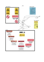
  Illustration 6 


   Illustration 7 


  Illustration 8   


         Illustration 9 


Summary of Contents for 2500

Page 1: ...GmbH Prichard s Nursery Equipment LLC Eysoelden M 41 P O Box 549 91177 Thalmaessing Portland TN 37148 Germany U S A Phone 49 9173 79 18 0 Phone 423 326 0753 Fax 49 9173 79 18 49 Fax 615 323 7667 eMail info opitz optimal com eMail sales optimaltreespades com web www opitz optimal com web www optimaltreespades com Serial Number 250021 ...

Page 2: ... S page Safety Instructions 3 1 Operating Specifications 4 2 Hydraulic Supply 5 3 Operation and Transport 6 4 Care and Maintenance 14 5 Lubrication chart 15 6 Hydraulic System 17 7 Wiring Diagram 19 8 Spare Parts List ...

Page 3: ...maintenance or repair work lower the tree spade to the ground and stop the engine of the power unit The tree spade must be inspected by an expert on operational reliability annually All hydraulic hose pipes must get replaced every six years Do not modify the equipment unless the manufacturer has given his approval Use original spare parts only When digging it might happen that a stone gets caught ...

Page 4: ... 3A Tower 4 Tower 1 Lock Cylinder Tower 2 3 5 Gate Cylinder Gate Cylinder Main Frame right and left ...

Page 5: ... 3B main lift arm drivers cabin rear stabilizer frame ...

Page 6: ...working height 303 cm 119 weights digging head 5750 kg superstructure 7800 kg hydraulics hydraulic working pressure 200 220 bar 2900 3190 psi oil flow 80 100 l min 21 1 26 4 GPM spade pressure at 200 bar 15000kg blade 33000lbs blade controls electro hydraulic valves double acting activated either from control panel in the driver s cabin by means of levers joystick and switch or from valve banks at...

Page 7: ... per ISO 4406 The first sampling and examination must be made after 50 working hours each following sampling becomes due after every 1000 working hours The intervals for changing the hydraulic oil must be strictly observed otherwise the durability of sealing components and hose pipes cannot be guaranteed In case the PANOLIN HLP SYNTH run hydraulic system is changed on a petroleum based hydraulic o...

Page 8: ... or feet inside the machine Do not tie the tree when it is inside the digging head When sight is limited an assistant must direct the driver by hand signals Before starting operations bolts and hydraulic fittings must be checked to make sure they are well tightened and free of damage When moving and working on public roads the relevant traffic rules and regulations must be adhered to IMPORTANT Bef...

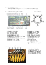
Page 9: ... up down 15 right spade rear up down 6 preselect folding out spades LH rear front 16 indicator light gate lock open 7 folding out spades in out 17 indicator light controls on 8 preselect folding out spades RH rear front 18 emergency off 9 rear stabilizer LH up down 19 oil supply min max 10 rear stabilizer RH up down 20 main lift arm up main lift arm down digging head rotation in out 21 articulated...

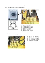
Page 10: ...LH up down 3 root ball pad RH up down 4 RH gate open close 5 gate lock unlock lock 6 folding out spades in out 3 1 4 Valve Bank at the Digging Head 5 functions 1 left spade rear up down 2 left spade front up down 3 right spade rear up down 4 right spade front up down 5 center spade up down ...

Page 11: ...m and the articulated lift arm must be raised and the digging head must be rotated out into a vertical position control panel joystick 20 main lift arm up control panel joystick 21 articulated lift arm up control panel joystick 20 digging head rotation out The functions main lift arm up articulated lift arm up and digging head rotate out must be actuated in repeating succession until the digging h...

Page 12: ... the circular frame of the digging head then close the gate control panel lever 2 LH gate close control panel lever 3 RH gate close Now the gate must get locked control panel lever 1 gate lock lock To ensure that the machine is digging only when the gate is locked a safety switch has been installed If the gate is not locked properly a red indicator light at the panel section 3 1 1 number 16 will f...

Page 13: ...regarded as a rule of thumb only since the actual working depth depends on the type of soil Whenever the blades encounter too much resistance by hard soil and the digging head is lifted up the next pair of opposite blades should be activated 3 2 7 The root ball pads are meant to support the coherence of the root ball Once the root ball has been dug the pads should be pressed gently on the root bal...

Page 14: ... collapsible When travelling long distances or when being transported on a low bed loader on public roads the frame can be folded up thus reducing the transport height see illustration 5 D Illustration 5 Illustration 5 1 To get tree spade Optimal 2500 into the transport position as shown above the following work must be performed Retract all spades to top position spades up and get digging head in...

Page 15: ...osition The main lift arm A is lowered until the upper edge of the lift arm is level with the RH side of mark D on base frame B An arrow indicates the RH side of the mark ill 5 5 1 control panel joystick 20 main lift arm down This position is for road transport only Do not move with collapsed digging head off road Illustration 6 Illustration 7 Illustration 8 Illustration 9 ...

Page 16: ...ed purity class 19 15 11 as defined by ISO 4406 the hydraulic oil must be changed This is extremely important because regular sampling is precondition for any damages claim The first sampling and examination must be made after 50 working hours each following sampling becomes due after every 1000 working hours 4 4 All hydraulic hose pipes must get inspected thoroughly at least once per year Defecti...

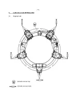
Page 17: ... 15 5 Lubrication chart OPTIMAL 2500 5 1 Digging head ...

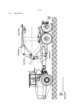
Page 18: ... 16 5 2 Superstructure ...

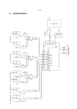
Page 19: ... 17 6 Hydraulic System 1 ...

Page 20: ... 18 6 Hydraulic System 2 ...

Page 21: ...s option This warranty does not cover any typical wear items such as guides This warranty cover damages to the hydraulic system and related components only if the purchaser can prove that the hydraulic oil was regularly sampled as stipulated under section 4 3 The owner is responsible for any repair costs arising due accident fire or objects damaging the tree spade or misuse as described in the Ope...

Reviews: