background image

Page 13

4. 

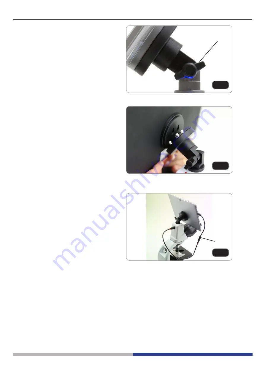
Fix the rotating part of the junction using 

the black wing-nut 

. (Fig. 13)


5. 

Then  hook  the  Tablet  PC  onto  the  4 

screws  of  the  junction  and  pull  toward 

down to firmly lock the Tablet PC in the 

holder. (Fig. 14)

•  To  unlock  the  Tablet  PC  proceed  with 

the  opposite  operation:  push  toward 

up  and  remove  it  from  the  holder.


6. 

Plug one side of the cable named CA

-

MERA CONNECTION (USB + OTG) 

② 

to the digital head and the other side to 

the Tablet PC. (Fig. 15).

7. 

Plug the cable named POWER SUPPLY 

CONNECTION to the Tablet PC for bat

-

tery recharge.


Fig. 13

Fig. 14

Your Tablet’s been set with the Rotation function disabled: this prevents any flipping of the Live View in order to 

get a continuous and as large as possible view of your slide also when the Tablet is removed from the holder. To 

enable this function again is very easy: you can activate the Rotation by swiping the screen on his bottom right 

side and selecting Se Screen. Anyway, it’s not suggested to activate the function when the camera is in 

Live View mode as it may give troubles when the camera runs at high resolutions.

The Tablet PC can be fixed to a junction.

Fig. 15

Summary of Contents for B-290 Series

Page 1: ...Model B 290 series B 292 B 292PLI B 293 B 293PLI B 290LD series B 292LD1 50 B 292LD1 B 293LD1 50 B 293LD1 B 290TB series B 290TB B 290 Series INSTRUCTION MANUAL Ver 3 0 2019...

Page 2: ...1 B 292LD1 50 B 293LD1 B 2932LD1 50 11 7 4 3 B 290TB 12 7 5 Polarizing set optional 14 8 Use of the microscope 15 8 1 Switching on the microscope 15 8 2 Light intensity adjustment 15 8 3 Coarse focus...

Page 3: ...s manual CAUTION This symbol indicates a potential risk and alerts you to proceed with caution ELECTRICAL SHOCK This symbol indicates a risk of electrical shock 3 Safety Information Avoiding Electrica...

Page 4: ...TUBE ONLY FOR TRINOCULAR HEAD INTENSITY ADJUSTMENT DIAL STAGE OBJECTIVES COARSE FOCUS KNOB CONDENSER X Y MOVEMENT KNOBS SLIDE HOLDER CONDENSER HEIGHT ADJUSTMENT KNOB CONDENSER CENTERING SCREWS OBSERV...

Page 5: ...KNOB FINE FOCUS KNOB CONDENSER SLIDE HOLDER CONDENSER HEIGHT ADJUSTMENT KNOB STAGE OBJECTIVES X Y MOVEMENT KNOBS CONDENSER CENTERING SCREWS EYEPIECES PHOTO TUBE ONLY FOR TRINOCULAR HEAD OBSERVATION H...

Page 6: ...3 B 290TB INTENSITY ADJUSTMENT DIAL COARSE FOCUS KNOB FINE FOCUS KNOB STAGE X Y MOVEMENT KNOBS SLIDE HOLDER OBJECTIVES DIGITAL HEAD TABLET EYEPIECES CONDENSER HEIGHT ADJUSTMENT KNOB CONDENSER CENTERIN...

Page 7: ...ner and put it on a stable desk Do not touch with bare hands optical surfaces such as lenses filters or glasses Traces of grease or other residuals may deteriorate the final image quality and corrode...

Page 8: ...ion head binocular B 292LD1 B 292LD1 50 trinocular B 293 B 293PLI Photo tube only B 293 series Eyepieces Objectives 10X 20X 40X 50X B 292LD1 50 B 293LD1 50 10X 20X 40X 100X dry B 292LD1 B 293LD1 Dust...

Page 9: ...90TB Frame Digital observation head Eyepieces Objectives 4X 10X 40X 100X Dust cover Green filter Immersion oil Power supply Tension adjustment tool Tablet power supply OTG cable USB cable Touch pen Ta...

Page 10: ...d and tighten the screw Fig 1 Hold the head with one hand during the lo cking in order to avoid that the head falls 3 Insert both eyepieces into the tubes of the optical head Fig 2 4 Insert the power...

Page 11: ...nd tighten the locking screw Fig 5 2 Insert the cable in the socket placed at the rear side of the microscope Fig 6 3 Insert the optical head above the stand and tighten the screw Fig 7 Hold the head...

Page 12: ...screw the photo tube Fig 4 7 4 3 B 290TB 1 Remove the dust cap from the microscope frame and from the bottom of the observation head 2 Insert the optical head above the stand and tighten the screw Fig...

Page 13: ...named POWER SUPPLY CONNECTION to the Tablet PC for bat tery recharge Fig 13 Fig 14 Your Tablet s been set with the Rotation function disabled this prevents any flipping of the Live View in order to ge...

Page 14: ...t at the base of the microscope Fig 16 2 Loosen the head fixing knob and remove the head from the microscope frame Fig 17 3 Insert the analyzer into the hole inside the frame Fig 18 4 Put back the hea...

Page 15: ...ion according to personal s needs rotate the ring using the provided tool Fig 21 Clockwise rotation increases the tension If the ten sion is too loose the stage could go lower by itself or the focus e...

Page 16: ...models except LD series 1 Focus the specimen with a low power objective 2 Lower the stage 3 Put a drop of oil provided on the area of the specimen to be observed Fig 25 Make sure that there are no oil...

Page 17: ...l the field of view is evenly illuminated in the field of view no dark and bright areas must be noticed 6 Fully open the diaphragm 8 9 Aperture diaphragm The Numerical Aperture N A value of the apertu...

Page 18: ...d in factory and doesn t need any alignment operation Focus on your sample and adjust the light intensity as needed through the brightness adjustment knob In order to improve the darkness of the backg...

Page 19: ...into the photo tube Fig 31 9 2 Reflex camera 1 Screw the T2 ring not provided at the end of the projection lens M 173 then install everything to the reflex camera Fig 32 2 Insert the projection lens i...

Page 20: ...e the specimen to a flat position One side of the image is out of focus The nosepiece is not in the center of the light path Turn the nosepiece to a click stop The specimen is out of place tilted Plac...

Page 21: ...n unico punto ma guardi l intero campo visivo a disposizione Peri odicamente distolga lo sguardo e guardi un punto distante dopodich torni ad analiz zare il campione V Microphotography Image edge is u...

Page 22: ...region The equipment has acquired the CE safety label However users do have full responsibility to use this equipment safely Cleaning the optics If the optical parts need to be cleaned try first to u...

Page 23: ...te The separate collection of this equipment at the end of its lifetime is or ganized and managed by the producer The user will have to contact the manufacturer and follow the rules that he adopted fo...

Page 24: ...92 info optikamicroscopes com www optikamicroscopes com OPTIKA Spain spain optikamicroscopes com OPTIKA USA usa optikamicroscopes com OPTIKA China china optikamicroscopes com OPTIKA India india optika...

Page 25: ...Modelli Serie B 290 B 292 B 292PLI B 293 B 293PLI Serie B 290LD B 292LD1 50 B 292LD1 B 293LD1 50 B 293LD1 Serie B 290TB Serie B 290 MANUALE DI ISTRUZIONI Ver 3 0 2019...

Page 26: ...1 B 292LD1 50 B 293LD1 B 2932LD1 50 35 7 4 3 B 290TB 36 7 5 Set di polarizzazione opzionale 38 8 Uso del microscopio 39 8 1 Accensione del microscopio 39 8 2 Regolazione intensit luminosa 39 8 3 Regol...

Page 27: ...rischio potenziale ed avverte di procedere con cautela SHOCK ELETTRICO Questo simbolo indica un rischio di shock elettrico 3 Informazioni sulla sicurezza Per evitare shock elettrici Prima di collegare...

Page 28: ...ICO SOLO PER TESTE TRINOCULARI MANOPOLA REGOLAZIONE INTENSIT TAVOLINO OBIETTIVI MANOPOLA MACROMETRICA DI MESSA A FUOCO CONDENSATORE MANOPOLE TRASLAZIONE X Y FERMAVETRINO MANOPOLA REGOLAZIONE ALTEZZA C...

Page 29: ...OMETRICA DI MESSA A FUOCO CONDENSATORE FERMAVETRINO MANOPOLA REGOLAZIONE ALTEZZA CONDENSATORE TAVOLINO OBIETTIVI MANOPOLE TRASLAZIONE X Y VITI DI CENTRAGGIO CONDENSATORE OCULARI TUBO FOTOGRAFICO SOLO...

Page 30: ...TENSIT MANOPOLA MICROMETRICA DI MESSA A FUOCO MANOPOLA MACROMETRICA DI MESSA A FUOCO TAVOLINO MANOPOLE TRASLAZIONE X Y FERMAVETRINO OBIETTIVI TESTA DIGITALE TABLET OCULARI MANOPOLA REGOLAZIONE ALTEZZA...

Page 31: ...base e appoggiarlo su un piano stabile Non toccare a mani nude superfici ottiche come lenti filtri o vetri Tracce di grasso o altri residui possono deteriorare la qualit dell immagine finale e corrode...

Page 32: ...azione binoculare B 292LD1 B 292LD1 50 trinoculare B 293 B 293PLI Tubo terza uscita solo serie B 293 Oculari Obiettivi 10X 20X 40X 50X B 292LD1 50 B 293LD1 50 10X 20X 40X 100X dry B 292LD1 B 293LD1 Co...

Page 33: ...i osservazione digitale Oculari Obiettivi 4X 10X 40X 100X Copertina Filtro verde Olio da immersione Alimentatore Chiave regolazione tensione Alimentatore tablet Cavo OTG Cavo USB Pennino per tablet Ta...

Page 34: ...saggio Fig 1 Tenere sempre la testata con una mano du rante il serraggio della vite per evitare che la stessa cada 3 Inserire gli oculari nei portaoculari vuoti della testa di osservazione Fig 2 4 Ins...

Page 35: ...ite Fig 5 2 Collegare il cavo al connettore posto nella parte posteriore dello stativo Fig 6 3 Inserire la testa sullo stativo e serrare la vite di fissaggio Fig 7 Tenere sempre la testata con una man...

Page 36: ...grafico Fig 10 7 4 3 B 290TB 1 Rimuovere il tappo di protezione dallo stativo e dalla parte sottostante della testa di osservazio ne 2 Inserire la testa sullo stativo e serrare la vite di fissaggio Fi...

Page 37: ...5 7 Collegare il cavo denominato POWER SUPPLY CONNECTION al Tablet per ricaricare la batte ria Fig 13 Fig 14 Fig 15 Questo Tablet stato impostato con la rotazione dello schermo disattivata questo evit...

Page 38: ...i cam po del microscopio Fig 16 2 Allentare la manopola di fissaggio della testa e rimuovere la testa di osservazione dallo stativo Fig 17 3 Inserire l analizzatore nella sede all interno dello stativ...

Page 39: ...one in base alle preferenze personali ruotare la ghiera utilizzando la chiavetta in dotazione Fig 21 La rotazione in senso orario aumenta la frizione La tensione troppo bassa se il tavolino scende da...

Page 40: ...tranne i modelli LD 1 Mettere a fuoco con un obiettivo a basso ingran dimento 2 Abbassare il tavolino 3 Mettere una goccia di olio in dotazione sulla zona del campione da osservare Fig 25 Assicurarsi...

Page 41: ...a che il campo visivo omogenea mente illuminato non si devono notare zone pi chiare o pi scure all interno del campo visivo 6 Al termine aprire competamente il diaframma 8 9 Diaframma di apertura Il v...

Page 42: ...e Inoltre la sorgente LED pre al lineata in fabbrica e non necessita di nessuna operazione aggiuntiva Mettere a fuoco il campione e regolare l intensi t della luce secondo le necessit attraverso la ma...

Page 43: ...nte di proiezio ne nel tubo vuoto della terza uscita Fig 31 9 2 Fotocamere Reflex 1 Avvitare l anello T2 non in dotazione all estre mit della lente di proiezione M 173 quindi colle garetuttol insiemea...

Page 44: ...e Per osservazioni in luce trasmes sa lo spessore del coprioggetto non deve superare gli 0 17mm Utilizzare un coprioggetto con spessore di 0 17mm La messa a fuoco non omoge nea Il portapreparati non p...

Page 45: ...in un unico punto ma guardi l intero campo visivo a disposizione Peri odicamente distolga lo sguardo e guardi un punto distante dopodich torni ad analiz zare il campione V Microfotografia Il bordo de...

Page 46: ...la zona in cui ci si trova ad operare Pulizia delle ottiche Qualora le ottiche necessitino di essere pulite utilizzare prima di tutto aria compressa Se questo non fosse sufficiente usare un panno non...

Page 47: ...giunta a fine vita organizzata e gestita dal produttore L utente che vorr disfarsi della presente apparecchiatura dovr quindi contattare il produttore e seguire il sistema che questo ha adottato per...

Page 48: ...optikamicroscopes com OPTIKA USA usa optikamicroscopes com OPTIKA China china optikamicroscopes com OPTIKA India india optikamicroscopes com OPTIKA Central America camerica optikamicroscopes com 100...

Reviews: