


35
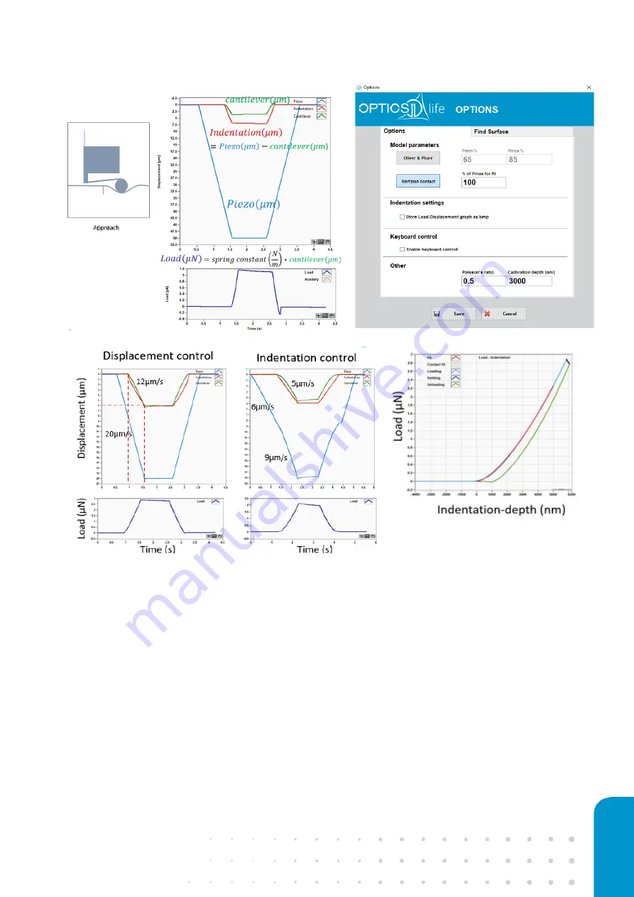
Figure 28
a) Measured signals of piezo movement and cantilever bending and calculated ones, indentation-depth and load, as
a function of time. b
) Options menu to set fitting parameters for the preliminary Young’s modulus values.
c) Displacement control
measurement where the set piezo speed is 20 µm/s and resulting indentation speed is 12 µm/s. d) Indentation control
measurement where set indentation speed is 5 µm/s, approach speed is 6 µm/s and resulting piezo speed is 9 µm/s e) Load-
indentation curve and Hertz fit in red.
Displacement control
–
D-mode
In D-mode, a piezo displacement profile is defined by the user. The indentation depth depends on the
distance from the sample surface and the ratio of cantilever and sample stiffness during piezo movement
while in contact with the sample. Since the piezo is not receiving any feedback signal from the sample
(cantilever bending), it is working in an open loop with the sample meaning one has no control over
indentation-speed, depth or load. The displacement (µm) and time (s) variables can be customized. A
maximum segment number of 12 can be defined, by default the segment number is set to 5 (
a).
When measuring the sample for the first time, always start with Displacement control to assess sample
and probe stiffness interaction. Keep in mind that displacement distance should be higher than the
distance to the sample (Z-above surf.). Time(s) will define how fast the piezo moves and is usually
a)
b)
c)
d)
e)


