background image


Step 6 

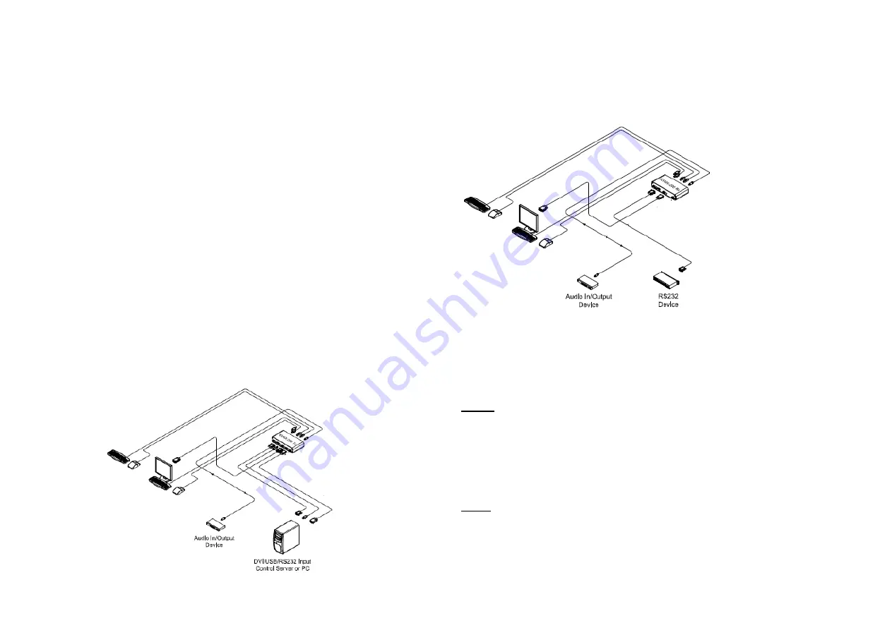
Connect  the  DVI  OUT  port  of  Receiver  to  a  DVI  display  over  a  DVI  copper  cable. 
Attach  keyboard  and  mouse  to  the  USB  HID  port  or  PS/2  port  for  remote  control. 
Then, the LED (blue) will be turned on.  
 
If  necessary,  connect  the  RS-232,  DIO,  audio,  and  mic  cables  to  RS-232,  DIO 
1IN/GND/2OUT,  audio  IN/OUT,  and  mic  IN/OUT  connectors  on  the  front  side  of 
Receiver.  


Figure 3

– Connection of Receiver 


Step 7 

Connect  one  (1)  LC  single-mode  fiber  to  an  Optic  port,  on  the  rear  side  of  the 
Transmitter and Receiver. Then, the Optic LED (blue) and Status LED (blue) on the 
front side of both will be turned on.  


Note1:


If you select two (2) fibers application, each fiber channel shall be connected 

as 1 to 1 and 2 to 2 carefully. 


Step 8 

If the connectors are fully engaged, a display will be shown. 


Note2

:  KVMX-200-TR  reads  EDID  information  of  both  local  side  and  remote  side 

displays  and  then,  determines  the  lowest  resolution  of  them  for  easy  and  flexible 
installation (Auto-mix EDID programming).  


1-4 Installation 


Installation 

Important: Please keep the installation procedure below.  Improper or no 
operation may result if the start-up sequence is not correctly followed. 


Step 1 

Carefully unpack the contents of the shipping group.  
 

Step 2  

Power on the PC and display(s). 
 

Step 3  

Plug  the  12V  power  adapters  to  the  +12V  DC  jack  on  the  rear  side  of 
Transmitter and Receiver. Then, the Power LED (blue) will be turned on. 
 

Step 4 

Connect the DVI IN port of Transmitter to the DVI output of a PC over a DVI 
copper cable. Connect USB IN port of Transmitter to PC over one (1) USB A-
B  cable  for  Keyboard  and  Mouse.  Then,  the  LED  (blue),  next  to the  USB  IN 
port will be turned on. 
 
If necessary, connect the RS-232, DIO, audio, and mic cables to RS-232, DIO 
1IN/GND/2OUT, audio IN/OUT, and mic IN/OUT connectors on the front side 
of Transmitter.  

 
Step 5  

Connect  the  Local  Display  port  of  Transmitter  to  a  DVI  display  over  a  DVI 
copper cable.  Attach keyboard and mouse to the USB HID port or PS/2 port 
for local control. Then, the LED (blue) will be turned on. You may skip Step 5 
if you don

’t need local control.  


Figure 2

– Connection of Transmitter 


1-3 Installation 


Summary of Contents for KVMX-200-TR

Page 1: ...cription 1 1 System Requirements for Setup 1 2 Installation 1 3 Switch Operation Guide 1 5 Troubleshooting Maintenance Technical Support 1 6 Product Specifications 1 7 Features Ordering Information 1 9 Warranty Information 1 10 Firmware download 1 11 Pictorials Figure 1 Connection Diagram 1 1 Figure 2 Connection of Transmitter 1 3 Figure 3 Connection of Receiver 1 4 1 0 Manual Contents ...

Page 2: ...erating the product Product Description New One 1 fiber DVI optical KVM extender KVMX 200 TR transmits DVI USB HID PS 2 RS 232 and bi directional stereo audio signal up to 1 0km 3 280feet over one 1 LC optical fiber As an option you can select one 1 or two 2 fibers connection by SFP module Designed for high resolution performance it guarantees lossless image quality and no frame dropping to delive...

Page 3: ...x EDID programming 1 4 Installation Installation Important Please keep the installation procedure below Improper or no operation may result if the start up sequence is not correctly followed Step 1 Carefully unpack the contents of the shipping group Step 2 Power on the PC and display s Step 3 Plug the 12V power adapters to the 12V DC jack on the rear side of Transmitter and Receiver Then the Power...

Page 4: ...data is always transmitted not only to Local Display but also to remote DVI OUT However USB port for keyboard and mouse is selectable for control at specific position Local control Set the switch on the front of the Transmitter to the Local side and the Local LED blue of both will be turned on Then you can control a PC at local side through the display connected to the Local Display port of the Tr...

Page 5: ...2 receptacle for local KM Two 2 USB A receptacle for remote KM Two 2 PS 2 receptacle for remote KM AUDIO 3 5mm jack Connector Tx Connector Rx One 1 Audio In One 1 Audio Out One 1 Mic In One 1 Mic Out One 1 Audio In One 1 Audio Out One 1 Mic In One 1 Mic Out DIO Connector Tx Connector Rx One 1 DIO In One 1 GND One 1 DIO Out One 1 DIO In One 1 GND One 1 DIO Out SERIAL DATA COMMUNICATION Connector Tx...

Page 6: ...hall not be treated as household waste Instead it shall be handed over to the applicable collection point for the recycling of electrical and electronic equipment By ensuring this product is disposed of correctly you will help prevent potential negative consequences for the environment and human health which could otherwise be caused by inappropriate waste handling of this product The recycling of...

Page 7: ...Step 4 Select shortcuts If you don t want it check the blank box Then click the Next button Step 5 Click Install button and then the installation will be completed Step 6 Check the box Launch Download GUI and click the Finish button Step 7 Then the Download GUI is completed to install the firmware download Step 8 Power on the Transmitter or Receiver and connect a PC to Service port on the front si...

Page 8: ... TR to run it under new firmware program 1 13 Firmware download 2020 Opticis Co Ltd All Rights Reserved Version 1 3 Dec 2020 Opticis Locations OPTICIS HQ Opticis Co Ltd 3F 305 Sanseong daero Sujeong gu Seongnam si Gyeonggi do 13354 South Korea Tel 82 31 719 8033 Fax 82 31 719 8032 www opticis com For order support please contact your Distributor or Reseller For technical support check with the Opt...

Reviews: