Self-EDID Programming Procedure
The graphic source equipment generally requires communication of display
information (EDID). Display information (EDID) contains resolution and timing
information for your display. Basically,
M5-1003 supports DDC2B with the
local display.
M5-1003 also offers Self-EDID programming.
Self-EDID programming
means that the EDID from the display is stored in the transmitter. You should
use Self-EDID feature if you
don’t connect local monitor. Follow these steps to
record the EDID of the display into the transmitter unit.
Note1
:
If you know that EDID is not required by the source, Auto-EDID
programming is not necessary.
Note2: The default EDID in factory ship-out is programmed in the VESA standard
of UXGA (1600x1200) @60Hz.
Step 1
Power on the display.
Step 2
Insert the included 12V DC power adapter into the transmitter.
Step 3
Push the EDID PRGM. button of the transmitter with a narrow pin.
After three
times blinking of Self-EDID LED, it will stay on
.
Self-EDID LED
EDID-PRGM. Button
Figure 9
– Position of EDID-PRGM. Button and Self-EDID LED
Step 4
Connect the Local Display port in transmitter to the display while turned
on over DVI cable.
The LED on the front panel will begin to blink rapidly.
Blinking indicates reading the EDID. LED will be turned OFF after blinking for
about 8 sec. The monitor EDID has been recorded.
Step 5
Disconnect the transmitter from the display. Then, LED ON again.
1-6 Self-EDID Programming Procedure
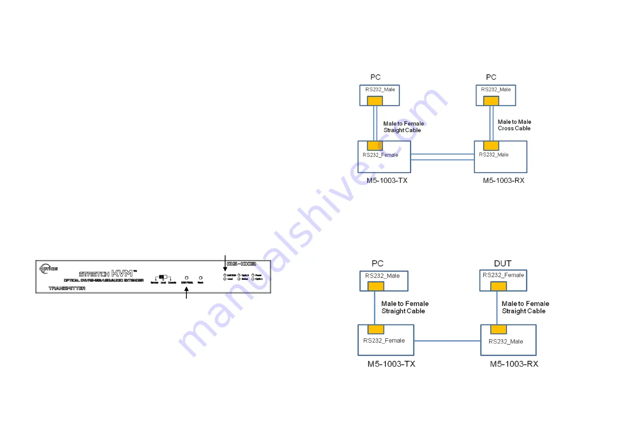
RS-232 Cabling
1. When you connect
PC to PC
over RS-232 with M5-1003, please use
male
to female straight type
cable between PC and M5-1003-TX and
male to
male cross type
cable between PC to M5-1003-RX.
2. When you connect
PC to RS-232 device (DUT)
over RS-232 with M5-
1003, please use
male to female straight type
cable between PC and M5-
1003-TX and
male to female straight type
cable between RS-232 device
to M5-1003-RX.
Figure 10
– Proper RS-232 cable type around M5-1003
1-7 RS-232 Cabling