


28
Correct tensioning is of special importance for the reliable and
efficient transmission of power. Proper tensioning of the stationary
belt will ensure that it will run at the correct tension.
●
Insufficient tension coupled to high drive loads will lead to the
belt jumping teeth on the pulley and ultimately to belt breakage.
●
Excessive tension under similar conditions will cause severe
wear, shearing of the belt teeth, excessive running noise and
bearing damage.
It is advisable therefore to calculate and set the static tension for
each drive individually using the formulae below. The tensioning
factor c
v
takes account of the loads combined in the overall service
factor c
2
.
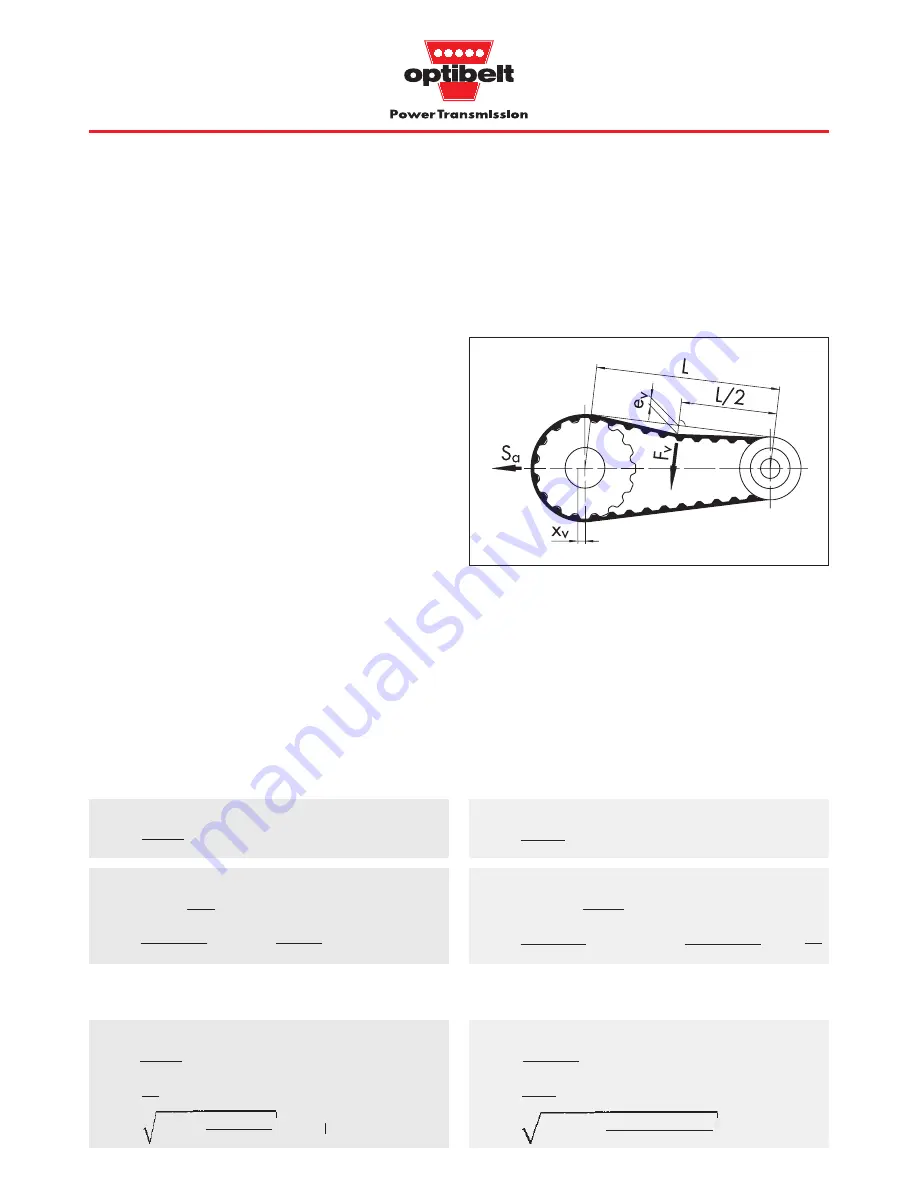
Setting the static tension
One pulley only of the drive may be fixed when the static tension
is adjusted. The second pulley and the other pulleys of a multiple
pulley drive must be able to rotate freely.
The test force F
v
should be applied in the centre of the span length
‘L’ perpendicular to it. Sharp-edged objects MUST not be used for
depressing the timing belt to avoid belt kink. Correct static tension
is achieved when the deflection e
v
corresponds to the calculated
value.
When the drive system has more than the two pulleys shown in
Figure 3.1 the tension can be measured between any two pulleys
in the system provided the belt is in contact with these pulleys with
the same face (top or bottom). The only difference will be e
v
which
will change as a function of span length.
3.5 ZRM/ZRP tensioning
Calculation and setting of tension for
optibelt
ZRM/ZRP
timing belt drives
Alternatively, the belt can be tensioned statically using the calcu-
lated static shaft load S
a
.
By virtue of the zero stretch tension cord, the belt will require no
further tension checks after fitting.
Tensioning
Test force F
v
and deflection e
v
for span length L
F
v
=
c
v
and S
n3
see above
e
v
=
L = a
nom
for i
U
1
L
=
a
nom2
–
for i
U
1
F
v
=
= 54 N
e
v
=
= 8.0 mm
L
=
408.71
2
–
= 401.05 mm
L
50
(d
wg
– d
wk
)
2
2
1.3 · 828
20
401.1
50
(190.98 – 79.58)
2
2
Static shaft load S
a
and centrifugal force S
n3
S
a
= c
v
· S
n3
L see below
S
n3
=
v
eff
=
formulae page 13
L
a
nom
S
a
= 1.3 · 828
= 1056 N
S
n3
=
= 828 N v
eff
=
= 6.04
5.0 · 1000
6.04
401.05
408.71
Tension factor and forces
Tension factor c
v
c
v
=
+ 0.9
1.05
≤
c
v
c
v
=
+ 0.9 = 1.3
1.8 – 1
2
Formulae
Example
(using the values from page 27)
79.58 · 1450
19100
m
s
For formula symbols, see also page 14
F
v
= load to set tension
(N)
S
n3
= centrifugal force
(N)
e
v
= span deflection under load F
v
(mm)
L
= span length
(mm)
d
w1
· n
1
19100
P
Ab
· 1000
v
eff
c
2
– 1
2
c
v
· S
n3
20
Figure 3.1: Adjusting belt tension
•
•
•
•
•
•
•
•
•
•
•
•
•
•
•
Summary of Contents for ZRL
Page 54: ...53 ...
Page 95: ...94 ZRM ZRP Data Sheet Notes ...


