


14
2 Basics of Drive Design
2.2 Symbols used in formulae
Table 2.4 defines the essential parameters and relevant units used
in the formulae listed on page 13, and the drive design process.
Table 2.4: Symbols
Symbol
Description
Unit
a
Required drive centre distance
(mm)
a
nom
Drive centre distance with standard belt length
(mm)
b
St
Standard belt width
(mm)
b
th
Theoretical belt width
(mm)
c
v
Tension factor
c
0
Basic service factor
c
2
Total service factor
c
2vorh
Actual service factor
c
3
Length factor
c
6
Pulley and idler correction factor
c
8
Correction factor for start/stop and
reversing under load
d
a
Outside diameter of pulley
(mm)
D
B
Outside diameter of pulley over flanges
(mm)
d
wg
Pitch diameter of the large pulley
(mm)
d
wk
Pitch diameter of the small pulley
(mm)
d
w1
Pitch diameter of the driver pulley
(mm)
d
w1th
Theoretical pitch diameter of the driver pulley
(mm)
d
w2
Pitch diameter of the driven pulley
(mm)
e
v
Belt deflection for checking belt tension
(mm)
F
v
Load used to set belt tension
(N)
i
Ratio required
i
eff
Ratio calculated from the number of pulley teeth
L
Span length
(mm)
L
wnom
Pitch length of joined endless/open ended
(mm)
timing belts (ZRL-V/ZRL-M)
L
wSt
Standard pitch length of endless
(mm)
timing belts (ZRM/ZRP)
L
wth
Theoretical pitch length of timing belts
(mm)
M
Ab
Torque
(Nm)
M
Abth
Theoretical torque
(Nm)
M
An
Driver torque
(Nm)
M
B
Design torque including service factor
(Nm)
M
Bth
Theoretical design torque
(Nm)
M
spez
Transferrable torque per engaged tooth
(Nm/cm)
and 10 mm belt width
n
k
Speed of small pulley
(min
-1
)
n
1
Speed of driver pulley
(min
-1
)
n
2
Required speed of driven pulley
(min
-1
)
n
2eff
Speed of driven pulley calculated from
(min
-1
)
the number of teeth
P
An
Driver power
(kW)
P
Ab
Driven power
(kW)
P
B
Design power including total service factor
(kW)
P
spez
Power per engaged tooth, 10 mm belt width
(W/cm)
and 1 tooth of the small pulley
S
a
Static shaft loading at correct tension
(N)
S
Bn3
Design circumferential force including
(N)
total service factor
S
n3
Circumferential force
(N)
S
spez
Transferrable circumferential force per
(N)
engaged tooth and 10 mm belt width
S
zul
Transferrable circumferential force at
(N)
maximum standard width
t
Tooth spacing
(mm)
v
Required belt speed
(m/s)
v
eff
Actual speed
(m/s)
x
Allowance for centre distance adjustment
(mm)
a
nom
for belt tensioning
x
v
Deflection at correct tension (ZRL-M/ZRL-V)
(mm)
y
1/2/3
Allowance for centre distance adjustment
(mm)
a
nom
for belt installation, determined from
pulley arrangement
z
e
Number of teeth in mesh with the small pulley –
for power transmission calculation
z
emax
Maximum number of teeth in mesh with the small
pulley – for power transmission calculation
z
enom
Number of teeth in mesh with the small pulley – actual
z
k
Number of teeth on the small pulley
z
R
Number of teeth on the timing belt
z
1
Number of teeth on the driver pulley
z
2
Number of teeth on the driven pulley
Symbol
Description
Unit
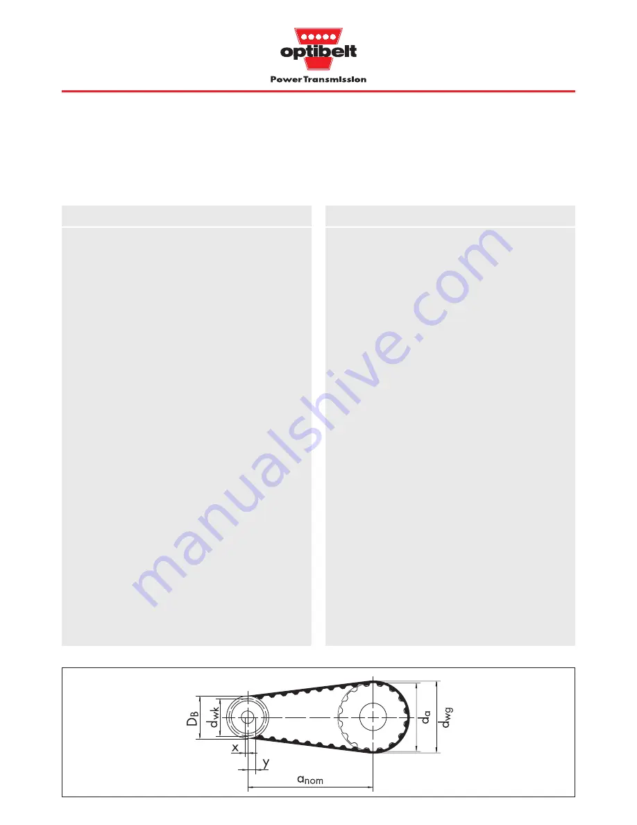
Fig.2.1: Drive arrangement
•
•
•
•
•
•
•
•
•
•
•
•
•
•
•
•
•
•
•
•
•
•
•
•
•
•
•
•
Summary of Contents for ZRL
Page 54: ...53 ...
Page 95: ...94 ZRM ZRP Data Sheet Notes ...


