Optelecom-nkf XSNet 2800 SW User Manual Download Page 3


3

DC

P10

P9

P3


P2


P1

1

2

3

6

8

9

4

10

1Gb

1Gb

2800

SW


P8


P7


P6


P5

P4


5

7

10/100 Mb


PLEASE READ THE DOCUMENT 'QUICK START' BEFORE INSTALLING THIS EQUIPMENT 


XSNet 2800 SW v.3 


Part I: description, features, hardware installation 


1. General description 
 

XSNet 2800 SW switches will handle eight electrical 
(Ethernet) data streams, and also provide two 
independent gigabit optical uplinks through SFP single-
mode or multimode packages using two fibres per port 
(wavelengths 850 nm, 1300 nm, or CWDM) or one 
fibre (SM-BiDi option, ca. 10 km). The switches are 
especially suitable for use in outdoor housings. 
The non-blocking, highly configurable switches support 
the following protocols: ARP, LLC, IP, UDP, IGMP, 
Spanning Tree (STP) and Rapid Spanning Tree 
(RSTP).  
Front panel status LEDs provide information about 
power, port speed and port activity. 
The switches come in the form of double-width (14TE) 
Eurocassettes fitting in MC 11 or similar power supply 
cabinets, or as stand-alone units (/SA option). Device 
configuration can be performed in-band using the built-
in http server. In-band device and link management 
using a GUI can be performed with the aid of 
Optelecom-NKF utility programs based on the MX 
protocol. In an EB-2 type power supply cabinet, the 
switches can be configured and managed with the SNM 
protocol [variable by name protocol not implemented].  


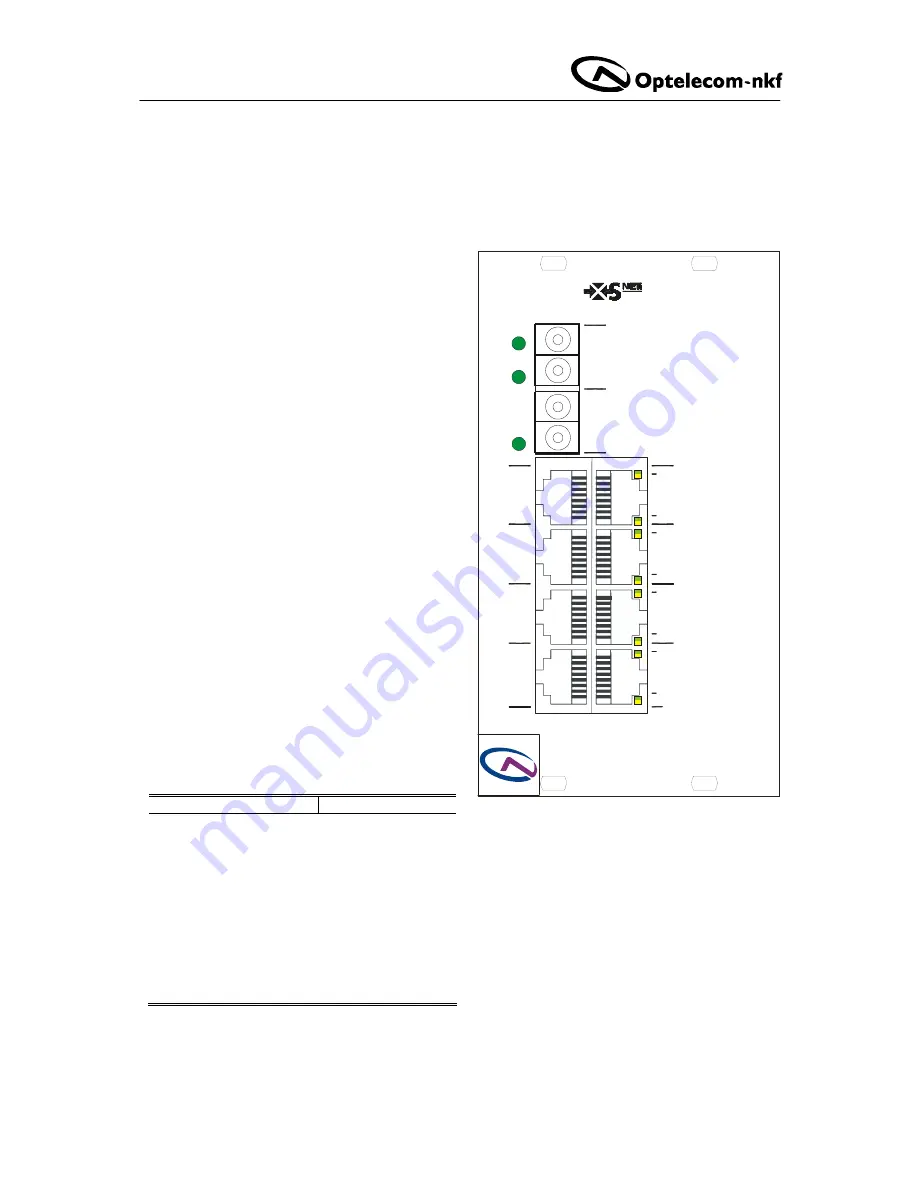
2. Front panel features 

 
The 2800 SW front panel, shown in figure 1, has 
features as listed in table 1 below and represented in 
figure 1. 
 

Feature Function 

Connectors 

Optical LC (dual), 9, 10 

optical Ethernet ports 

RJ45, jack, 8x (1-8)  

10/100TX Ethernet ports 

Status LEDs 


*DC

                             green  DC power OK 


link speed 10 Mbit/s 
blinking: data activity 


link speed 100 Mbit/s 
blinking: data activity 


*P1

-

*P8


yellow 


green 

 
      off  no connection 


*P9

*P10


 green  green: sync OK 

blink: data activity 
off: no sync received 

Table 1. Front panel connectors and indications 

Figure 1. XSNet 2800 SW front panel 

Summary of Contents for XSNet 2800 SW

Page 1: ...XSNet 2800 SW Firmware v 3 Field hardened layer 2 Ethernet switch with 2 optical Gbit uplinks 8 10 100Base T ports USER MANUAL Optelecom NKF 2006 Version v 1 0b 060203 1b XSNet2800SWv3 MW03SP2...

Page 2: ...et 2800 network settings 8 4 XSNet 2800 SW alarms 9 5 2800 SW VLANs 10 VLAN Control and VLAN Port Control 11 Settings example 12 Application example 13 6 XSNet 2800 SW Quality of Service QoS 14 7 XSNe...

Page 3: ...form of double width 14TE Eurocassettes fitting in MC 11 or similar power supply cabinets or as stand alone units SA option Device configuration can be performed in band using the built in http serve...

Page 4: ...circulation moisture lockout and prevention of dust or grime accumulation are always desirable The switch will power up in a few seconds performing auto negotiation on the 100 Mbit ports The Spanning...

Page 5: ...ware A standard Web browser will suffice to find the module by its IP address Activate the LOGIN button on the login screen that will appear see figure 1 below After the Connect box appears see below...

Page 6: ...o another active device panes sections showing parameter values some of which are editable buttons mainly SAVE REFRESH and CANCEL for sections with editable fields Writing changes into the device afte...

Page 7: ...Module status field On this page only the 32 character labels can be edited please activate the SAVE button if after making changes you wish to make them definitive and active However if you decide to...

Page 8: ...and Gateway settings show subnet mask and default gateway Assuming the device IP address and subnet mask are already set correctly only the default gateway needs to be defined in order to connect the...

Page 9: ...also means the alarm will actually go off if a certain condition is met For the 2800 SW these conditions are Power supply alarm Indicates an active power supply alarm 2V5 or 3V3 outside 5 of their nom...

Page 10: ...f more than one VLAN is of course allowed untag i e remove Q tags indicating that tags holding VLAN and priority information should be removed from the output For a port connected to another switch th...

Page 11: ...ress rules set in the VLAN Port Control pane see figures 8 and 11 If VLANs are enabled the following ingress options are available incoming Q tagged frames can be modified as follows see figure 9 they...

Page 12: ...e 11 If set this has prevalence over tag insertion or modification Settings example With VLANs enabled a port connected to another switch a non edge port generally would be set to drop non Q frames in...

Page 13: ...g to the device for computers connected to SW1 ports 5 6 and SW2 ports 7 8 similarly use VLAN ID 5 Both switches ports 9 ingress Q frames must be left as they are non Q frames are to be blocked egress...

Page 14: ...al to the TCI threshold and up go into the high priority queue TCI tag control information Fulfilling either of these two conditions see the arrows in figure 13 will get a frame into the high priority...

Page 15: ...manager Often these are public mainly used for the read and trap communities and private or netman for read write operations The manager software may offer additional choices Traps Traps generated by...

Page 16: ...ber of variables can be read out and in a few cases be edited and set Many 2800 SW variables are contained in the system and interfaces sections of RFC1213 MIB Others are found in RFC1493 bridge MIB R...

Page 17: ...vice Viewed from the root device all ports connecting to the root ports of designated switches are assigned as designated ports After determining the lowest cost spanning tree the RSTP enables all roo...

Page 18: ...t port The allowed range is between 0 255 Its default setting is 128 The lowest number has the highest priority Path Cost Specifies the path cost of the port The Switch uses this to determine which po...

Page 19: ...partake in the STP configuration the ports are all forwarding see figure 18 To force full compatibility with STP only equipment from the start you will need additional MX configuration software set t...

Page 20: ...h handles multicasting Transmitter mode the switch will block all outgoing multicast traffic for this port Multicast traffic entering the port from outside will pass so this is a switch entry port for...

Page 21: ...setting duplex half duplex and link speed per port manually The negotiation results appear in the speed duplex and pause the switch is able to send and receive pause frames columns If auto negotiatio...

Page 22: ...loads are represented in figure 21 Transmit and receive port loads are shown in terms of maximum loads per port in the upper two graphs while received packet size and error statistics are depicted in...

Page 23: ...age however always makes the switch reboot with the option Reboot the switch will retain all its settings when rebooting with the option Keep settings under Restore default settings figure 24 This can...

Page 24: ...operational any setting will do nothing reboot keep settings reboot the switch without changing settings reboot restore factory defaults resets all values erase network settings and reboot keep setti...

Page 25: ...use the equipment to be more prone to fail EMC requirements Non video signal lines must use appropriate shielded CAT5 cabling S FTP or at least an equivalent If system components such as cabling e g c...

Reviews: