background image

Managing Operators and Jobs

73

Model 72™ Operator Manual

OPEX Corporation

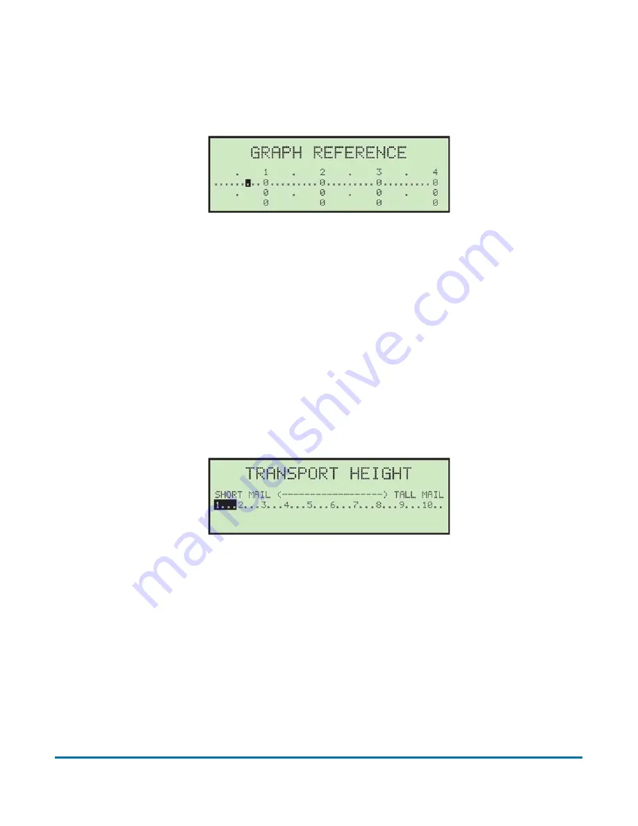
 5.4.6. GRAPH REFERENCE

During run mode, a graph is displayed that shows an operator's performance 
(Figure 5-31).


Figure 5-31: Graph Reference screen

A horizontal line, representing the average or target rate is also displayed. The 
graph shows counts of 1000, 2000, 3000 and 4000 envelopes. Each 100 
increment between is represented by a dot. The target rate can be set by 
moving the cursor with the right and left arrows and pressing 

Enter

. Values 

may be changed in increments of 100. Figure 5-31 shows a target rate of 700 
per hour. Press 

Cancel

 to exit this screen.

 5.4.7. TRANSPORT HEIGHT

This job parameter is used to set the main transport height (Figure 5-32). 

Figure 5-32: Transport Height screen

Transport height can be set on a scale from 1 (short mail) to 10 (tall mail). The 
transport height can be adjusted by moving the cursor with the right and left 
arrows and pressing 

Enter

.

The Transport Height scale from 1-10 corresponds to 0.2875” (7.3025 mm) 
increments from 3.5” (88.9 mm) to 6.375” (161.925 mm).

Mathematically in inches: (6.375-3.5)/10= 0.2875

Mathematically in millimeters: (161.925-88.9)/10= 7.3025

Summary of Contents for Model 72

Page 1: ...ers partners and dealers No portion of these materials may be reproduced published or stored in a database or retrieval system other than for its intended use without the express written consent of OP...

Page 2: ...f the product ready see Model Serial Number Location on page 33 For other inquiries OPEX Corporation 305 Commerce Dr Moorestown NJ 08057 4234 USA Tel 1 856 727 1100 Fax 1 856 727 1955 https www opex c...

Page 3: ...dress 835 Lancer Drive Moorestown New Jersey 08057 4225 United States of America Importer s Name OPEX Corporation Importer s Address 29 32 Queensbrook Bolton Technology Exchange Spa Road Bolton BL1 4A...

Page 4: ...Lancer Drive Moorestown New Jersey 08057 4234 United States of America Importer s Name OPEX Corporation Importer s Address Parc Technopolis ZA de Courtaboeuf 3 avenue du Canada Les Ulis France Type o...

Page 5: ...ss 835 Lancer Drive Moorestown New Jersey 08057 4225 United States of America Importer s Name OPEX Corporation Importer s Address SAP Partnerport Altrottstrasse 31 69190 Walldorf Germany Type of Equip...

Page 6: ...hroughout document Page 1 Updated look of title page adding document revision Page 6 Added new Document History table page 66 specifications for Japanese Model 72s have been added 21 01 July 26 2021 D...

Page 7: ...edure to load envelopes Page 53 Stopping a job section added Page 71 added hybrid mail height option Page 73 improved graphic reference description Page 80 improved description for Display Graph Page...

Page 8: ...ter 1 Introduction 1 1 About the Manual 12 1 1 1 Manual navigation aids 12 1 1 2 Model 72 documentation 12 1 2 Safety Message Conventions 13 Chapter 2 Safety 2 1 Introduction 16 2 2 Safety Guidelines...

Page 9: ...ing a job 51 4 10 Stopping a job 53 Chapter 5 Managing Operators and Jobs 5 1 Managing Operators 57 5 2 Change Operator List 58 5 2 1 Add Operator 59 5 2 2 Delete Operator 60 5 2 3 Change Operator 60...

Page 10: ...6 5 6 Supervisor Statistics 77 5 6 1 Display Data 78 5 6 2 Graph Reference 78 5 6 3 Update Clock 79 5 6 4 Display Graph 80 5 6 5 Reset Data 81 5 6 6 Print Data 81 Chapter 6 Maintenance 6 1 Adjust LCD...

Page 11: ...Model 72 Operator Manual 1 Introduction 1 1 About the Manual 12 1 1 1 Manual navigation aids 12 1 1 2 Model 72 documentation 12 1 2 Safety Message Conventions 13...

Page 12: ...ronic release of the manual for your reference The latest release can be downloaded in PDF format at www opexservice com 1 1 1 Manual navigation aids This manual is designed primarily for use on a tab...

Page 13: ...e Model 72 DANGER Indicates a hazardous situation that if not avoided will result in death or severe injury The use of this signal word is limited to the most extreme situations WARNING Indicates a ha...

Page 14: ...14 Introduction Model 72 Operator Manual OPEX Corporation This page is intentionally blank...

Page 15: ...Model 72 Operator Manual 2 Safety 2 1 Introduction 16 2 2 Safety Guidelines 17 2 2 1 Maintenance Safety 19 2 3 Model 72 Safety Labels 20 2 4 Ergonomics 26...

Page 16: ...ues regarding the operation and maintenance of the OPEX Model 72 described in this manual This chapter provides an explanation of the safety guidelines to be observed when working with the Model 72 id...

Page 17: ...create a pinch point between the desk and your body The height ships by default in the lowest position Figure 2 1 Safety Guidelines Transport Height the transport height is adjustable per job when se...

Page 18: ...e carried out by persons authorized to do so in accordance with a safe system of work Do not attempt to clean the Model 72 while it is running A cloth or similar material should never be used to clean...

Page 19: ...e service or repairs Maintain the Model 72 according to the scheduled preventive maintenance procedures provided in this manual Follow applicable service and repair procedures provided in this manual...

Page 20: ...e the Model 72 is operating Bilingual English Spanish labels for US Model 72s Bilingual English French labels for Canadian Model 72s Graphics only labels for EU and various international Model 72s no...

Page 21: ...2 serial number Note that the Ratings Serial Number labels in the right column show the WEEE symbol This indicates that Waste Electrical Electronics Equipment should be disposed of at an authorized re...

Page 22: ...l Label locations Description United States FCC 7682610 Japan only MIC registration 7682640 Contains FCC ID VDM2054710 Contains IC 7175A 2054710 Model 205471010 OPEX Corporation This device complies w...

Page 23: ...l OPEX Corporation 2 3 0 3 Pinch Point Caution Label Location The beginning of the feed path Table 2 3 Purpose Warns about pinch hazards within the feed path Table 2 3 Pinch Point Caution label Label...

Page 24: ...test label Location Inside the cabinet door Table 2 4 Purpose To inform personnel that the ground points in the Model 72 are well connected between each other and it has passed the ground bond test Ta...

Page 25: ...ual OPEX Corporation 2 3 0 5 Ground Symbol Location On the inside of the frame near the power panel Table 2 5 Purpose Identifies Ground cable connection point Table 2 5 Ground Symbol label Label locat...

Page 26: ...an upright body posture Occasionally change the angle of your posture for greater comfort Avoid operating the Model 72 for longer than a single 8 hour shift If possible stretch between breaks If your...

Page 27: ...2 Operator Manual 3 Overview 3 1 Model 72 Components and Features 28 3 2 Power Panel 31 3 2 1 Software options 32 3 3 Model Serial Number Location 33 3 4 Specifications 34 3 4 1 Electrical Specificati...

Page 28: ...d fashion Before using the Model 72 take time to familiarize yourself with its main components and features see Figure 3 1 and Table 3 1 Figure 3 1 Model 72 components LCD Screen Top cutter under cove...

Page 29: ...stem minimizes reach and can be adjusted to various heights Sort tray offers additional sorting capabilities Button keypad controls Used for navigating the menus and starting stopping the Model 72 Adj...

Page 30: ...rameters Cycle and Verifier Lights The green cycle button is illuminated when the Model 72 is turned on The red verifier light flashes if contents are detected Optional Printer Provides a hard copy of...

Page 31: ...ver maintenance is performed The main power has a 10 Amp circuit breaker Accessory Outlet Use with low current items 1A or less Note This is a North American option only Accessory Outlet Circuit Break...

Page 32: ...tegrated using OPEX Network Solution ONS software This allows machine parameters job parameters and operator information to be read from or written to the Model 72 by a central computer In addition vi...

Page 33: ...rial Number Location Before contacting OPEX Technical Support locate the Model Serial label on your Model 72 so that you can provide the assisting technician with your Reference Serial Number Figure 3...

Page 34: ...161 925 mm Envelope Length 5 to 11 5 127 mm to 292 1 mm Envelope Thickness up to 3 8 9 525 mm Physical Specifications Length side to side 6 feet 4 inches 76 inches 1930 4 mm Depth front to back 3 feet...

Page 35: ...EU 220 240VAC 50HZ 1 Phase JP 100VAC 50 60HZ Input Current NA 9 25A Max EU 4 50A Max JP 7 50A Circuit Breaker NA 10A EU 5A JP 10A Accessory Outlet NEMA 15R Grounded Receptacle 1A Max Accessory Outlet...

Page 36: ...36 Overview Model 72 Operator Manual OPEX Corporation This page is intentionally blank...

Page 37: ...onality 38 4 2 Enhanced Scrolling 40 4 3 Powering up 40 4 4 Logging in 41 4 4 1 Changing Operator Passwords 43 4 5 Selecting a job 45 4 6 Operator Statistics 46 4 7 Loading envelopes 48 4 8 Setting cu...

Page 38: ...ill allow you to navigate up through a column of data When the upper item within the column is highlighted and you press the up key the list of data is shifted down by a row and the previous line of d...

Page 39: ...is pressed then the last item in the previous row will be selected In addition if the first item on the page is highlighted and the left arrow is pressed the list is shifted down and the previous line...

Page 40: ...en Figure 4 2 The scroll bar indicates were the cursor is in relation to the top and bottom of the list Figure 4 2 Typical enhanced scrolling screen 4 3 Powering up 1 Turn the main power switch locate...

Page 41: ...gure 4 4 Figure 4 4 Login screen 2 Press the Enter button on the keypad to display the SELECT OPERATOR screen OPEX provides two default operators NEW and SUPERVISOR When new operators are added by a S...

Page 42: ...perator the ENTER PASSWORD screen will be displayed next see Figure 4 7 Figure 4 7 Enter Password screen 6 Use the Arrow keys and the Enter button to enter a password An asterisk will be displayed in...

Page 43: ...ll not be prompted to enter their current password before entering a new password Supervisor login has the ability to view and change operator passwords To change a password 1 After logging in select...

Page 44: ...er their current password before setting their new password Use the keypad to enter the current password Once the correct current password has been entered navigate to SAV and press Enter on the keypa...

Page 45: ...he Model 72 there may be additional steps as explained in Locating a job when many are stored on page 65 5 Use the Arrow buttons to choose a job and press Enter to select it Based on the job settings...

Page 46: ...ically start printing the information selected The printing status will be displayed on the screen during printing operations Note Supervisor level users can view and print all operator statistics For...

Page 47: ...press Enter Figure 4 17 Select Time Range screen 4 Using the navigation buttons select and highlight the desired view or print function Figure 4 18 and press Enter Figure 4 18 Display Statistics scree...

Page 48: ...touching the belts Note It is not necessary to justify envelopes to the left conveyor wall 3 Slide the Mail Pusher to its most forward position Load a handful of mail behind the pusher using the side...

Page 49: ...it into place behind the last envelope The first envelope should be right in front of the feeder belts 5 Continue to load the mail placing each handful behind the pusher until the conveyor is full 6...

Page 50: ...0 No Cut knob fully left POSITION 1 Normal 0 060 0 1 52 mm POSITION 2 Normal 015 0 38 mm POSITION 3 Normal 030 0 76 mm POSITION 4 Normal 094 2 39 mm knob fully right The side cutter has four positions...

Page 51: ...during the current job A graphical representation of an operator s performance is updated every minute at the bottom of the run time display Three one hour windows are displayed and automatically shi...

Page 52: ...end the empty envelope to the verifier The next envelope will arrive at the extractor for the operator to remove contents and the Model 72 will automatically continue envelope cycling until ending the...

Page 53: ...y the same operator as a single run The two runs must occur within a predetermined timeout period set by your service technician or system administrator Pushing the Cancel button will temporarily susp...

Page 54: ...54 Operation Model 72 Operator Manual OPEX Corporation This page is intentionally blank...

Page 55: ...62 5 3 Creating Jobs 63 5 3 1 Adding a new job 64 5 3 2 Locating a job when many are stored 65 5 4 Job Parameters 67 5 4 1 JOB NAME 68 5 4 2 ACTIVATION MODE 68 5 4 3 EXTRACT POSITION 70 5 4 4 MAIL HE...

Page 56: ...56 Managing Operators and Jobs Model 72 Operator Manual OPEX Corporation 5 6 2 Graph Reference 78 5 6 3 Update Clock 79 5 6 4 Display Graph 80 5 6 5 Reset Data 81 5 6 6 Print Data 81...

Page 57: ...1 Figure 5 1 Supervisor main menu Log in as Supervisor using the login procedure The SUPERVISOR main menu will appear This screen is where all the supervisor tasks can be launched The following tasks...

Page 58: ...operator options DELETE select an operator from the operator list and delete CHANGE select an existing operator from the operator list and modify the operator s options SELECT select an operator from...

Page 59: ...press Enter on the keypad Pushing the Cancel button on the keypad will end the operator creation process Once saved the following screen appears Figure 5 4 Figure 5 4 Place Cursor Over New Location sc...

Page 60: ...e supervisor can select an operator from the operator list and delete them 1 On the CHANGE OPERATOR LIST screen select DELETE The SELECT OPER TO DELETE screen appears Figure 5 6 Figure 5 6 Select Oper...

Page 61: ...5 2 4 Select Operator 1 The supervisor can select an operator from the operator list The selected operator will become the current operator 1 On the CHANGE OPERATOR LIST screen choose SELECT The SELEC...

Page 62: ...GE OPERATOR LIST screen Figure 5 11 Figure 5 11 Change Operator List screen You must be logged in as supervisor to print out the report Note If you want to print information for a specific operator yo...

Page 63: ...creen ADD enter a new job and setup the job options DELETE select a job from the job list and delete CHANGE select an existing job from the job list and modify the job s options SELECT select a job fr...

Page 64: ...ow buttons to navigate through the on screen keypad Once entered navigate to SAV and press Enter on the keypad Pushing the Cancel button on the keypad will end the job creation process Once saved the...

Page 65: ...creens that can be used to help locate a specific job quickly see Figure 5 16 The SELECT JOB PAGE screen left can display multiple pages of jobs in alpha numerical order After selecting a desired job...

Page 66: ...press Enter Figure 5 18 Figure 5 18 Main Menu The SELECT JOB PAGE screen appears Figure 5 19 Figure 5 19 Select Job Page screen 2 Use the Arrow buttons and press Enter to select job page AMEX001 TD00...

Page 67: ...se the Arrows to select CHANGE JOB LIST and press Enter The CHANGE JOB LIST screen appears 2 Select CHANGE and press Enter The SELECT JOB TO CHANGE screen appears Figure 5 21 Figure 5 21 Select Job To...

Page 68: ...orted to the Verifier To make an activation mode change use the Arrow buttons to select ACTIVATION MODE in the SELECT JOB OPTION menu and press Enter The SELECT ACTIVATION menu will appear and the cur...

Page 69: ...n a change of thickness representing the removal of at least one sheet of paper is detected This has the advantage of handling a wide variety of envelopes and decreases the problems associated with va...

Page 70: ...erifier Then the next envelope will feed to the extraction area Figure 5 26 Time Out activation mode screen 5 4 3 EXTRACT POSITION On the SELECT JOB OPTION screen use the arrow buttons to highlight EX...

Page 71: ...eatly improve performance For example if uniform mail is run in varying height mode the shuttle will move home center of travel before each piece and then move down or up to accommodate the height of...

Page 72: ...ariations in thickness between envelopes USE FIRST ENVELOPE AS REFERENCE This allows the first envelope to set the standard for each envelope that follows USE 16 ENVELOPE AVERAGE AS REFERENCE This use...

Page 73: ...rrows and pressing Enter Values may be changed in increments of 100 Figure 5 31 shows a target rate of 700 per hour Press Cancel to exit this screen 5 4 7 TRANSPORT HEIGHT This job parameter is used t...

Page 74: ...y moving the cursor with the right and left arrows from 1 small opening to 10 large opening and pressing Enter 5 4 9 SIDE TOP CUT OPTION These job parameters are used to identify where the cutters sho...

Page 75: ...ces are available from the CHANGE JOB LIST screen Figure 5 36 Figure 5 36 Change Job List screen Note If you want to print information for a specific job you will be presented with an additional scree...

Page 76: ...he passwords are set to enabled ALLOW OPERATOR PASSWORDS Which means the operator or supervisor will be prompted to enter a password if one already exists To disable operator and or supervisor passwor...

Page 77: ...ics 1 Log in as supervisor The SUPERVISOR Main Menu appears Figure 5 39 Figure 5 39 Supervisor Main Menu 2 Use the arrow buttons to highlight STATISTICS MENU and press Enter The STATISTICS menu appear...

Page 78: ...JOB REPORT displays statistics for each job INDIVIDUAL RUN displays individual statistics for each job run SUMMARY REPORT displays statistics for all jobs OPERATOR REPORT displays statistics for each...

Page 79: ...resents an increase of 100 envelopes per hour Once the target rate is set press Enter Note For more on this parameter see page 73 5 6 3 Update Clock This is used to update the Model 72 clock 1 In the...

Page 80: ...5 25 2021 with no mail processed but the Model 72 was last run on 5 21 2021 and 5 24 2021 then the first line of the display will show 05 21 21 and the second line will show 05 24 21 If mail was run...

Page 81: ...key to erase and reset all statistical data 5 6 6 Print Data In the supervisor STATISTICS Menu selecting PRINT DATA opens the PRINT STATISTICS window where you can choose from the following options D...

Page 82: ...82 Managing Operators and Jobs Model 72 Operator Manual OPEX Corporation This page is intentionally blank...

Page 83: ...Manual 6 Maintenance 6 1 Adjust LCD Contrast 84 6 2 Adjusting the desk height if enabled 85 6 3 Routine Maintenance 87 6 4 Emptying the Cutter Trash 88 6 5 Changing the Feeder belts 89 6 6 Changing t...

Page 84: ...ess the Left button The adjust intensity screen appears Figure 6 1 Figure 6 1 Adjust intensity screen 3 Use the Up Down buttons to darken or lighten the display as desired A numerical value in the low...

Page 85: ...e Login Run and Pre Run screens alert you that it is possible to raise or lower the desktop work surface see Figure 6 2 Figure 6 2 Lift system enabled Note If the Lift System machine parameter is not...

Page 86: ...n screen Up or Down arrow will highlight when the table is in motion see Figure 6 3 Figure 6 3 Lift system in motion moving up The table will continue to move until the Up Down button is released the...

Page 87: ...l 72 DO NOT USE aerosol cleaners or compressed air because of the flammable nature of many of these products There is a risk of malfunction and or injury associated with the use of aerosol cleaners pr...

Page 88: ...collected in a trash bin located inside the door to the operator s right see Figure 6 4 The bins should be checked and emptied on a regular basis Failure to empty trash bins will result in chips hayst...

Page 89: ...need to be replaced 1 Carefully remove the cover from the feeder area by lifting it up and away from the Model 72 Figure 6 5 Figure 6 5 Front cover 2 Loosen the thumb screw on the feed guide and push...

Page 90: ...belts 7333934 in the same location as the older belts 5 Return the guide to its original position and tighten the thumb screw 6 Replace the front cover making sure to align the holes in the cover wit...

Page 91: ...it will need to be replaced Figure 6 8 Figure 6 8 Changing the retard tire 3 Push slightly on the roller so that it is not pressed tightly against the friction feeder 4 Pull the rubber tire off the r...

Page 92: ...92 Maintenance Model 72 Operator Manual OPEX Corporation This page is intentionally blank...

Page 93: ...Model 72 Operator Manual 7 Troubleshooting 7 1 Sensors 94 7 2 Error messages 95...

Page 94: ...ht settings for the lift system Figure 7 1 Figure 7 1 Sensor locations Verifier Entry Top Cut Path Extract Open Extract TX Upper Just Lower Just Extract RX Shuttle Piece RX TX Shuttle Home Interlock 2...

Page 95: ...to the Feed Exit sensor in 2 5 seconds Some possible causes for this may be that there is a paper jam the feed motor is not running the feed clutch is not engaging or the nip rollers between the Feed...

Page 96: ...P CUTTER If an envelope moves from the shuttle to the top cutter and the lead edge is not seen within a defined amount of time this error message appears This is often caused by the cleat running bene...

Page 97: ...Place a service call 14 EARLY REMOVAL OF CONTENT AT EXTRACT Once the envelope has stopped in the extract and the cups have opened the extract sensor must be blocked by at least two sheets of paper If...

Page 98: ...the mail is set up correctly on the conveyor and that the pusher is in the correct position If you still get this error place a service call 19 REMOVE ENVELOPE CHECK FOR CONTENTS Not currently used 2...

Page 99: ...the transport must first move all the way up then move down the necessary amount There is a defined nominal amount of time that it takes to move the transport from its highest to lowest position The t...

Page 100: ...the maximum current allowed by the output board Place a service call 30 FEED EXIT SENSOR BLOCKED TOO LONG This is called when the time it takes an envelope that is traveling past the Feed Exit sensor...

Page 101: ...PLEASE CLEAR LOWER JUSTIFIER SENSOR This jam is called when the Lower Justifier sensor is blocked during the start of Model 72 run Clear the feed tray area 36 FEED TRAY PIECE DETECTION TIMEOUT This j...

Page 102: ...oblem persists 40 INVALID MACHINE STATE DETECTED This jam is called when the upper level Smart Driver software receives an invalid state from the controller Place a service call if the problem persist...

Page 103: ...iness challenges for both today and tomorrow Our scalable Warehouse Document and Mail Automation solutions improve workflow accelerate change and drive efficiencies in infrastructure We are a family o...

Page 104: ...OPEX Corporation 305 Commerce Drive Moorestown NJ 08057 4234 USA http www opex com...

Reviews: