Openpath Core Series Installation Manual Download Page 27


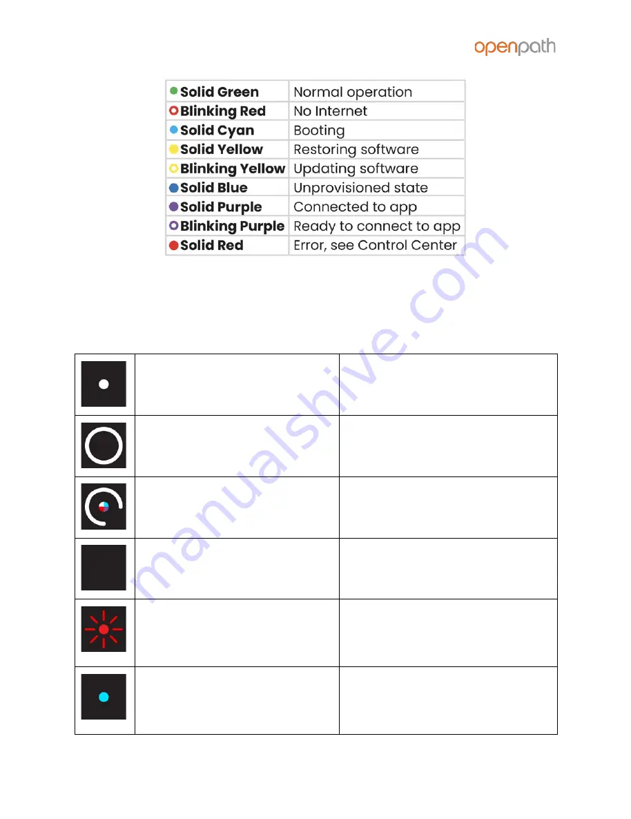
Figure   21 :   Core   Status   LED   Definitions  

READER   LEDS  

The   Openpath   Smart   Reader’s   LEDs   indicate   the   following:  


center   dot   =   solid   white  

door   is   locked  


outer   ring   =   solid   white  

door   is   unlocked  


center   dot   quickly   switches  

between   multiple   colors   and  

outer   ring   quickly   spins   once  

reader   has   just   received   power  


all   lights   are   off  

reader   is   not   connected   to   power  

(check   to   see   if   power   wires   are  

swapped)  


center   dot   is   flashing   red  

reader   is   connected   to   power   but  

cannot   communicate   with   the   ACU  

(check   to   see   if   the   +B   [blue]   and   -A  

[violet]   lines   are   swapped)  


center   dot   is   solid   blue  

reader   is   connected   to   power   and  

can   communicate   with   the   ACU,   but  

has   not   been   configured   as   an   entry  

in   the   Control   Center  


Version   1.8  

©  

  Openpath   2020  

Page   27  


All manuals and user guides at all-guides.com

Summary of Contents for Core Series

Page 1: ...OPENPATH ACCESS CONTROL SYSTEM INSTALLATION GUIDE V1 8 All manuals and user guides at all guides com a l l g u i d e s c o m ...

Page 2: ...DOOR SMART HUB WIRING WITH THE 12 24V POWER SUPPLY WIRING THE REX WITH THE DOOR STRIKE WIRING THE REX WITH THE ELECTROMAGNETIC LOCK WIRING FAIL SAFE AND FAIL SECURE LOCKING HARDWARE WIRING THE OPENPATH ELEVATOR BOARD TO A STANDALONE CONTROLLER BOARD ADVANCED CONFIGURATIONS CHANGING I O TYPES WIRING TO LEGACY PANELS AND MOBILE GATEWAY WIRING TO WIEGAND DEVICES ON CORE SERIES SMART HUBS END OF LINE ...

Page 3: ...V Installation Guide Life Safety Power B100 Installation Guide Life Safety Power C4 Installation Guide PRIOR TO INSTALLATION Prior to installing Openpath hardware perform a customer site survey to determine the following How many entries need to be configured e g doors gates and or elevator floors Whether you re using legacy wiring or new wiring What kind of electronic entry mechanisms Request to ...

Page 4: ...he router firewall or NAT device is not required SELECTING A BACKUP BATTERY While not required Openpath recommends having a backup battery in case of power outages The size of battery depends on your setup and how long you want to power the system Table 1 Power requirements for legacy Smart Hubs 12V Controller board 1A Smart Reader 0 25A Locking hardware while engaged 0 25A 0 5A Assuming a 12V pow...

Page 5: ... mount the enclosure to the wall 1 Optional Remove the enclosure s cover 2 Locate the top keyhole mounting holes in the back of the enclosure 3 Mark and pre drill the locations for the keyholes in the mounting surface 4 Partially install two fasteners appropriate for the surface on which the enclosure is being installed Leave the heads of the fasteners approximately out from the surface Minimum fa...

Page 6: ...bs into holes in back of enclosure 3 Mount Elevator IO Board if included below the Core Board using 6 32 screws insert screws from back of enclosure with USB port on the left 4 Connect Core Board to 4 Port Board with included USB cable Connect Core Board to Elevator IO Board with additional USB cable Figure 1 E1 Board Placement Version 1 8 Openpath 2020 Page 6 All manuals and user guides at all gu...

Page 7: ...enclosure 2 Mount Core Board with the USB and Ethernet ports facing up as shown in the diagram and hook the tabs on into the holes in the enclosure and slide to the left to lock in place 3 Connect Core Board to 8 Port with included USB cable Figure 2 E2 Board Placement Version 1 8 Openpath 2020 Page 7 All manuals and user guides at all guides com ...

Page 8: ...the LifeSafety Power E1 enclosure FPV4 power supply B100 secondary power supply and C4 power control module 1 Follow all LifeSafety Power instructions for installing the FPV4 B100 and C4 in the enclosure 2 Mount the Controller Board using the provided back plate 3 Connect the B100 secondary supply to the Controller Board IMPORTANT Verify that the jumper on the B100 is set to 12V 4 Mount the enclos...

Page 9: ...instructions for installing the power supply in the enclosure 2 Mount the Controller Board using the provided back plate 3 Connect the power supply to the Controller Board IMPORTANT Verify that the jumper on the FPV4 is set to 12V 4 Mount the enclosure according to mounting instructions above Figure 4 First gen 12V Smart Hub ACU configuration Version 1 8 Openpath 2020 Page 9 All manuals and user g...

Page 10: ... of the drain wire the shield around the wires to the GND terminal on the ACU Both the shield and the GND wire can share the same GND terminal Do not connect the other side of the shield to anything For standard reader installation We recommend that you install a 1 Gang 20 CU box in order to flush mount the reader Alternatively the reader may also be surface mounted with the included back plate No...

Page 11: ... DOOR SMART HUB The Core Series 24V 4 Door Smart Hub 4ENT SYS 24V uses an FPV4 to power the Core and 4 Port Board Figure 5 4ENT SYS 24V Wiring Diagram Version 1 8 Openpath 2020 Page 11 All manuals and user guides at all guides com a l l g u i d e s c o m ...

Page 12: ...Smart Hub 4ENT SYS 1224V uses an FPV4 to power the Core and 4 Port Board a B100 secondary power supply and a C4 Control Module to power 12 24V locking hardware Figure 6 4ENT SYS 1224V Wiring Diagram Version 1 8 Openpath 2020 Page 12 All manuals and user guides at all guides com ...

Page 13: ...HUB The Core Series 24V Elevator Smart Hub 20ENT SYS 24V uses an FPV4 to power the Core 4 Port Board and 16 I O Elevator Board Figure 7 20ENT SYS 24V Wiring Diagram Version 1 8 Openpath 2020 Page 13 All manuals and user guides at all guides com ...

Page 14: ...etween 3V and 24V The inputs will not respond directly to a switch or relay connection to ground To use these inputs with a switch or relay connect one side of the switch to the input and the other side of the switch to a supply voltage between 3V and 24V If desired you can add a 1k ohm resistor in series with the switch Figure 8 Elevator Board Wiring Diagram Version 1 8 Openpath 2020 Page 14 All ...

Page 15: ...Smart Hub 8ENT SYS 1224V uses an FPV6 to power the Core and 8 Port Board a B100 secondary power supply and a C8 Control Module to power 12 24V locking hardware Figure 9 8ENT SYS 1224V Wiring Diagram Version 1 8 Openpath 2020 Page 15 All manuals and user guides at all guides com ...

Page 16: ...locking hardware Figure 10 OP 4ESH 24V Wiring Diagram This example contains An Openpath Reader on READER 1 port also connected to a Wiegand reader optional A door contact sensor on CONTACT 1 port A REX on REX 1 port A 24V fail secure door strike on RELAY 3 A 12V fail safe electromagnetic lock on RELAY 1 Version 1 8 Openpath 2020 Page 16 All manuals and user guides at all guides com a l l g u i d e...

Page 17: ... to the Entry For the example above you d need to add an additional Entry Exit Hardware Control to the Entry For more information refer to the Openpath User Guide WIRING THE REX WITH THE DOOR STRIKE Except where required by fire or safety codes for convenience you can wire the REX in parallel with the Door Strike on the same Relay output You can wire additional REXs to the REX inputs on the ACU as...

Page 18: ...ou must wire the REX directly to the electromagnetic lock You can wire additional REX switches and sensors to the REX inputs on the ACU as shown in figure 10 Figure 12 Wiring the REX with the Mag Lock Version 1 8 Openpath 2020 Page 18 All manuals and user guides at all guides com ...

Page 19: ...hen power is interrupted Figure 13 Wiring Fail Safe and Fail Secure Locking Hardware Note Some door strikes can be wired as fail safe and some electromagnetic locks can be fail secure always check your third party locking hardware wiring instructions and ensure you re using the right configuration for your requirements Version 1 8 Openpath 2020 Page 19 All manuals and user guides at all guides com...

Page 20: ...E OPENPATH ELEVATOR BOARD TO A STANDALONE CONTROLLER BOARD Figure 14 Wiring the Openpath Elevator Board to a Standalone Controller Version 1 8 Openpath 2020 Page 20 All manuals and user guides at all guides com ...

Page 21: ... PANELS AND MOBILE GATEWAY To add mobile credential features to a legacy access control system 1 Install the Openpath ACU between the Openpath Readers and the legacy panel with the ACU s Wiegand port or AUX I O configured as Wiegand configured as output to the legacy panel see Configuring Wiegand Devices in the Control Center 2 Replace low frequency LF Wiegand readers with LF Openpath Readers and ...

Page 22: ... WARNING Do not connect 12V out on the Wiegand port to the legacy panel doing this will cause voltage backfeeding potentially damaging one of the supplies Version 1 8 Openpath 2020 Page 22 All manuals and user guides at all guides com ...

Page 23: ...l openpath com and log in 2 Go to Hardware ACU Management then click on the ACU to edit it 3 Click on the Ports tab 4 Click Port next to the first input of the I O pair with a Wiegand device configured in this example AUX1 5 Select Wiegand Device from the Input Type dropdown then click Save This will label the subsequent input as Wiegand Device Extended and disable it from editing Inputs cannot be...

Page 24: ...th User Guide END OF LINE SUPERVISION 4 Port and 8 Port Board inputs have support for user installed single or double 1k ohm termination This lets you monitor cut or shorted lines and create alerts and rules in the Control Center The input settings in the Control Center must match the physical wiring configurations Figure 19 EOL configurations and settings Version 1 8 Openpath 2020 Page 24 All man...

Page 25: ...lick Cable next to the port with EOL configured 5 Select the appropriate End of Line Supervision setting from the dropdown then click Save Troubleshooting ACU LEDS READER LEDS LEGACY WIRING RESETTING THE ACU PROVISIONING THE ACU ACU LEDS Figure 20 Controller Board Expansion Board and Core LEDs Version 1 8 Openpath 2020 Page 25 All manuals and user guides at all guides com ...

Page 26: ...OARD ID LEDs match the Expansion Board Number in the Control Center CORE STATUS LED The Core s STATUS LED indicates the following Solid Green indicates the Core is provisioned and functioning normally Blinking Red indicates there is a problem with the Internet connection Solid Cyan appears when the Core is booting Solid Yellow indicates that the Core is restoring software appears when you power on...

Page 27: ... received power all lights are off reader is not connected to power check to see if power wires are swapped center dot is flashing red reader is connected to power but cannot communicate with the ACU check to see if the B blue and A violet lines are swapped center dot is solid blue reader is connected to power and can communicate with the ACU but has not been configured as an entry in the Control ...

Page 28: ...ults in slower connections and dropped packets between the Openpath Reader and ACU To remedy this you can switch GND and VIN with B and A connections on the ACU and readers to ensure the data pair B and A are using the alternate pair of legacy wires RESETTING THE ACU SOFT RESET To soft reset the ACU disconnect power from the ACU wait 10 seconds then reconnect the power HARD RESET WARNING Only hard...

Page 29: ...ONING THE ACU Provisioning the ACU means registering it in the Control Center and getting it up and running with the latest firmware You will need to re provision in the case of RESETTING THE ACU Note If you re provisioning ACUs for a customer account the customer org will need to be created by Openpath first REQUIREMENTS Meet all NETWORK REQUIREMENTS Connect the ACU to the Internet via Ethernet I...

Page 30: ... for the controllers b From the Controller Type dropdowns select the appropriate types i Legacy ACU for first gen Smart Hubs ii Single Door Controller SDC iii Core Series ACU for Core Series Smart Hubs c Enter the number of expansion boards connected to the controllers then select the types used Core Series Smart Hubs typically require at least one expansion board i Openpath 4 Port Expansion ii Op...

Page 31: ...ber for the ACU 5 Tap Test Internet Connection and wait for a green YES to appear before proceeding with the next step a Note This checks if the ACU SDC can ping https api openpath com health 6 Tap Provision Device 7 Tap on the ACU Name that you want to provision to this is the name of the ACU you created in the Control Center then tap Yes to proceed 8 The app will send notifications when ACU prov...

Page 32: ...If using an IPv4 address paste before 8080 For example 192 0 2 0 8080 ii If using an IPv6 address delete the last two digits and the percentage sign put square brackets outside the address and paste before 8080 Correct a123 b456 5a18 eb8f 7fd6 8080 Incorrect a123 b456 5a18 eb8f 7fd6 29 8080 iii Hit Enter then click the Provision button iv If the Provision button still doesn t appear contact Openpa...

Page 33: ... compliance requirements a separation distance of at least 20 cm should be maintained between the antenna of Openpath Smart Reader s and persons during operation NOTE This equipment has been tested and found to comply with the limits for a Class A digital device pursuant to part 15 of the FCC Rules These limits are designed to provide reasonable protection against harmful interference when the equ...

Page 34: ... Under Industry Canada regulations this radio transmitter may only operate using an antenna of a type and maximum or lesser gain approved for the transmitter by Industry Canada To reduce potential radio interference to other users the antenna type and its gain should be so chosen that the equivalent isotropically radiated power e i r p is not more than that necessary for successful communication C...

Page 35: ...teur de l appareil doit accepter tout brouillage radioélectrique subi même si le brouillage est susceptible d en compromettre le fonctionnement Warnings Disconnect power before servicing Do not plug into an outlet controlled by an on off switch Powering power supply with 230V requires jumper modification see power supply data sheet for more information Version 1 8 Openpath 2020 Page 35 All manuals...

Page 36: ...0 25A OP RLF STD MULB FCC ID 2APJVOPRLF OP RHF STD MULB FCC ID 2APJVOPRHF Standalone Controller Board OP 4ECTR 10 14VDC 1A 16 I O Elevator Board OP 16EM 12 24VDC 0 35A 12V 0 2 24V 4 Port Board OP EX 4E 12 24VDC 0 4A 24V 8 Port Board OP EX 8E 12 24VDC 0 6A 24V Access Control Core OP ACC 12 24VDC 0 4A 12V 0 2A 24V Version 1 8 Openpath 2020 Page 36 All manuals and user guides at all guides com a l l ...

Reviews: