background image

O p a l e - P a r a m o d e l s . c o m

Opale Aero System SARL - 23 rue de la Motte

62250 MARQUISE - France

[email protected] +33(0)981 144 387

PO

WER 1.1

PO

WER 1.1

Radio Setup

Connect the backpack servos (or pilot ones) to the radio receiver.  Think of removing the propeller before 

handling.

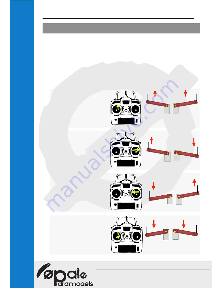
To fly the wing effectively, your radio must absolutely include a “Delta/V-Tail” mixer.

In case of using a non-programmable radio, you will have to use an additional module between the receiv-

er and the two servos, to do this mix. It is necessary to add a rubber band on the left stick (in Mode 1) in 

order to maintain constantly in flight the arms in high position. 

The amplitude of clearance of each servos must be 90° on a full clearance with each stick.

The V-tail mixer offers the advantage to fly the wing as a real.

As below:

Flight position maximum speed : 

the trajectory is rectlinear

Right turn: 

right arm move downwards, left 

arm move upwards

Left turn: 

Right arm move upwards, left 

arm move downwards.

Flight position minimum speed: 

both arms move downwards

Summary of Contents for POWER 1.1

Page 1: ... a r a m o d e l s c o m Opale Aero System SARL 23 rue de la Motte 62250 MARQUISE France contact opale paramodels com 33 0 981 144 387 2015 v1 0 User s manual Merci de lire ce manuel avant la première utilisation ...

Page 2: ...olled paraglider Best regards The Opale Paramodels Team Safety Information You should be properly insured according to the country regulation you are using our equipment in You hereby accept the inherent risk of flying radio controlled models Using our equipment in a bad way may increase risks Neither Opale Paramodels nor any other seller will be liable for any damage caused by any accident whatev...

Page 3: ...44 387 POWER 1 1 Wing composition Specifications Flat wingspan 236cm Ratio 5 1 Flat surface 1 1m2 Bridle Spliced Aramid 50daN DFL 70 Tissue Nylon Ultra light 20D 32gr Cells 23 Space between risers 10 to 16cm Total weight incl RTF Backpack 1kg 1 5kg 2kg 2 7kg 3 4kg Wind speed 5km h 10km h 15km h 20km h 30km h Upperskin Bridles Risers Ribs 3 ...

Page 4: ... have to use an additional module between the receiv er and the two servos to do this mix It is necessary to add a rubber band on the left stick in Mode 1 in order to maintain constantly in flight the arms in high position The amplitude of clearance of each servos must be 90 on a full clearance with each stick The V tail mixer offers the advantage to fly the wing as a real As below Flight position...

Page 5: ...le attachment ring on the riser Put the backpack in flight attitude so the servos in high position push ing the depth stick Then make a knot in a shoelace style to ensure its attachment at the arm s endpoint FIrst step Put the servos in high position and perform an inflat ing by pulling the backpack in a horizontal way If the wing encounters difficulties to inflate increase brake s length until yo...

Page 6: ...tant to optimize the wing s longevity It is strongly recommended to fold it acording to the following method valid for any wing Bring the wing s endpoints to the center of the wing Put the risers at the bottom of the central cells in order not to mix the bridle and avoid any overflowing Then bend the wing in two taking care of not folding the stabilizing rushes Then insert the wing in its carry ba...

Page 7: ... to remove the air Replace a damaged bridle Arm yourself with the raw material included with your wing Natural color Aramid is 25 daN It is used for the bridle connected to the wing on the clip Red Aramid is 50 daN used to connect the 25 daN bridle and the risers link If a bridle is cut it is important to use exactly the same material and redo as before the same length to the millimeter by respect...

Page 8: ...O p a l e P a r a m o d e l s c o m Opale Aero System SARL 23 rue de la Motte 62250 MARQUISE France contact opale paramodels com 33 0 981 144 387 POWER 1 1 Bridle Layout 8 ...

Page 9: ...600 a3 682 c3 524 k3 413 B3 800 a4 689 c4 537 k4 408 a5 677 c5 517 k5 377 C1 700 a6 670 c6 507 k6 353 C2 700 a7 667 c7 506 k7 349 C3 800 a8 456 c8 393 k8 362 a9 434 c9 376 k9 352 K1 600 200 a10 417 c10 364 k10 352 k11 356 KM1 350 b1 646 d1 574 KM2 350 b2 629 d2 554 t1 344 KM3 350 b3 627 d3 551 t2 339 b4 636 d4 563 t3 340 b5 623 d5 539 t4 347 b6 617 d6 524 b7 617 d7 518 A1 600 b8 407 d8 402 A2 600 ...

Page 10: ...se it is the bulged portion and non cutting side of the propeller The trailing edge must be directed backwards It is the cutting part of the propeller Generally propellers have a logo or a marking It is most of the time put on the leading edge How to inflate correctly his RC paramotor wing To inflate correctly his wing it is essential to face it to the wind at a sufficient distance from any obstac...

Page 11: ... is solidly attached to the backpack The wear of a helmet and flysuit is advised If you per form several 360 and wingovers think of install under the batteries a little plastig bag near its paws with few menthol candies Can I do another use of the paramotor wing This wing can be used for slope soaring without backpack In that case you will have to attach a pilot as real paraglider discipline Is it...

Reviews: