background image

39

Connecting Components not Reached by the Remote 
Controller Signals (IR IN/OUT)

In order to use the remote controller to control the 
receiver from a remote location, you will need to 
prepare a multiroom kit (sold separately) such as one 
listed below:
• Multiroom A/V distribution and control system such 

as those from Niles

®

 and Xantech

®

* Xantech is a registered trademark of Xantech Corporation.

* Niles is a registered trademark of Niles Audio Corporation.

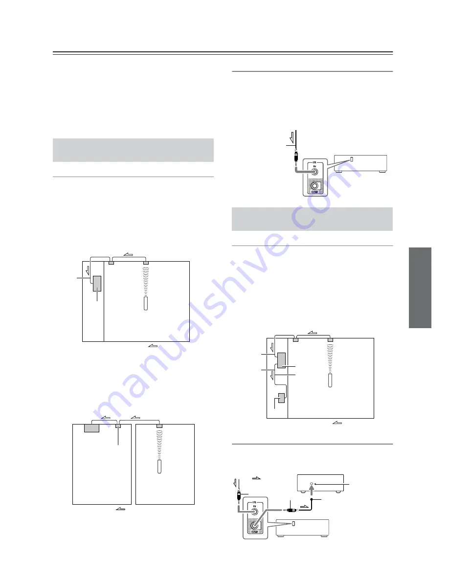
Effective Sensor Layout

Example for the main room

If the receiver is located inside a cabinet or other 
enclosure where the infrared rays from the remote 
controller cannot enter, then operation with the remote 
controller will not be possible. In such a case, it will be 
necessary to install a remote sensor at a location outside 
of the cabinet so that the infrared rays from the controller 
can be sensed.

Example for Zone 2

The IR IN input allows you to control the receiver from 
Zone 2 with the remote controller even though Zone 2 
may be on the other side of the building from the main 
zone. The diagram below shows how to make the proper 
connections for Zone 2.

Making Sensor Connections

When you place the IR receiver in the main room, connect 
the cable from the connecting block to the IR IN terminal.
Make the connection as shown below. Do not plug any 
equipment into the power outlet until all the connections 
are complete.

Effective Sensor Layout

In this situation, you will need to use a commercially 
available IR emitter. Connect the mini plug of the IR 
emitter to the IR OUT terminal on the receiver and then 
place the IR emitter on the remote sensor of the 
component or facing it. When the IR emitter is 
connected, only the signal input to the IR IN terminal is 
output to the IR OUT terminal. The signal input from the 
remote sensor on the front of the receiver will not be 
output to the IR OUT terminal.

Making Sensor Connections

The IR emitter should be connected to the receiver’s IR 
OUT Terminal, as shown below. 

If Remote Controller Signal Does not 
Reach the Receiver Remote Sensor

Connecting 
block

IR Receiver

Remote controller

IR IN

Receiver

In the 
cabinet

: Signal flow

Main room

IR Receiver

Remote controller

Connecting 
block

Receiver

Main room

Zone 2

: Signal flow

To IR IN

If Remote Controller Signal Does not 
Reach Other Components

Receiver

from connecting block

Mini plug cable

IR Receiver

Remote controller

Connecting 
block

IR IN

IR OUT

IR Emitter

Receiver

Other
component

: Signal flow

: Signal flow

Other component

Emitter

Remote control 
sensor

IR Emitter

Mini plug

Receiver

Mini plug

Summary of Contents for TX-8555

Page 1: ...king connections and plugging in the unit Following the instructions in this manual will enable you to obtain optimum performance and listening enjoyment from your new Stereo Receiver Please retain th...

Page 2: ...atus does not operate normally by following the operating instructions Adjust only those controls that are covered by the operating instructions as an improper adjustment of other controls may result...

Page 3: ...e original packaging to pack it how it was when you originally bought it Do not leave rubber or plastic items on this unit for a long time because they may leave marks on the case This unit s top and...

Page 4: ...which is marked with the letter L or coloured red IMPORTANT The plug is fitted with an appropriate fuse If the fuse needs to be replaced the replacement fuse must approved by ASTA or BSI to BS1362 an...

Page 5: ...ng Audio Sources 23 Muting the receiver remote controller only 24 Using Headphones 24 Setting the Display Brightness 24 Using the Sleep Timer remote controller only 24 Using the Tone and Balance Contr...

Page 6: ...ntroller for a long time remove the batteries to prevent damage from leakage or corrosion Expired batteries should be removed as soon as possible to prevent damage from leakage or corrosion Remote con...

Page 7: ...CBL SAT DVD VCR DVR Phono Input 2 Audio and Video Outputs Speaker A B Terminals Direct Mode Pure Audio Mode RDS PS PTY RT TP European model IR Input Output Banana Plug Compatible Speaker Posts North...

Page 8: ...and the display disappears when this mode is selected I TUNING UP DOWN buttons 28 Used for radio tuning J DIRECT TUNING button 29 When you know the frequency for the station you want to listen to you...

Page 9: ...e connected to the IR IN jack allowing you to control the receiver while you re in Zone 2 or control it when it s out of sight for example installed in a cabinet A commercially available IR emitter ca...

Page 10: ...r detailed information see the pages in parentheses 1 A and B speaker indicators Indicator A lights up when speaker set A is on Indicator B lights up when speaker set B is on 2 MUTING indicator Flashe...

Page 11: ...o G TUNING buttons 28 Used for radio tuning H SP A B button 23 Used for speaker A B setting I Arrow and ENTER buttons 28 Used to select and adjust settings For XM SIRIUS the Up and Down buttons are us...

Page 12: ...nt lights Keep this in mind when installing If another remote controller of the same type is used in the same room or the receiver is installed close to equipment that uses infrared rays the remote co...

Page 13: ...tection circuit may be activated resulting in no sound output from speakers The following illustration shows which speaker should be connected to each pair of terminals Read the instructions supplied...

Page 14: ...e PRE OUT SUBWOOFER to the amp s input If you want to use a more powerful power amplifier and use the receiver as a preamp connect it to the PRE OUT jacks and connect all speakers and the subwoofer to...

Page 15: ...he Speaker Impedance 1 Turn on the power 2 Press the RECEIVER button and then the SETUP button on the remote controller RECEIVER ENTER SET UP 3 Use the Up and Down buttons to select 1 Hardware set and...

Page 16: ...e into an FM radio station and adjust the position of the FM antenna to achieve the best possible reception 2 Use thumbtacks or something similar to fix the FM antenna into position Caution Be careful...

Page 17: ...cal regulations to prevent electrical shock hazards Using a TV FM Antenna Splitter It s best not to use the same antenna for both FM and TV reception as this can cause interference problems If circums...

Page 18: ...good connection loose connections can cause noise or malfunctions The receiver s PHONO input jacks are for use with moving magnet MM type cartridges Use an analog audio cable to connect the receiver...

Page 19: ...nput display name to HDD you can operate the RI Dock using the remote controller supplied with the receiver see page 22 Note Set the RI Dock s MODE switch to HDD or HDD DOCK Use an analog audio cable...

Page 20: ...connect other Onkyo components to the receiver with the appropriate and audio cables you can use the following system functions cables are special cables solely for use with Onkyo products no cables...

Page 21: ...on so that they turn on and off as and when the receiver is turned on and set to Standby Caution Make sure that the total capacity of the components that you connect to theAC OUTLETS does not exceed...

Page 22: ...ller s ON STANDBY button The receiver comes on the display lights up and the STANDBY indicator goes off To turn the receiver off press the ON STANDBY button or press the remote controller s ON STANDBY...

Page 23: ...ller To select the speaker set press the SP A B button repeatedly Note for North American model When you connect a set of speakers whose impedance is 4 or 6 ohms and output sound only from this speake...

Page 24: ...EEP button while the sleep time is being displayed you ll shorten the sleep time by 10 minutes PHONES SLEEP MUTING DIMMER Muting the receiver remote controller only 1 Press the remote controller s MUT...

Page 25: ...ction is off the tone controls can be used to adjust the sound When the DIRECT function is on the tone controls are bypassed so you can enjoy a pure sound You can configure whether the DIRECT function...

Page 26: ...lder copyright laws prohibit using your recordings for anything other than personal enjoyment Input selector buttons Recording the Input Source 1 Prepare the recorder Set the recorder so that it s rea...

Page 27: ...amcorder connected to the DVD IN jack are recorded by the VCR connected to the VCR DVR OUT jacks Recording Audio and Video from Separate Sources 1 Prepare the camcorder and CD player for playback 2 Pr...

Page 28: ...tor button to select AM or FM In this example FM has been selected Actual display depends on country and Release the button Receiver Band Frequency 2 Press the TUNING MODE button so that the AUTO indi...

Page 29: ...8 seconds use the number buttons to enter the frequency of the radio station For example to tune to 87 5 FM press 8 7 5 1 Tune into the AM FM station that you want to store as a preset 2 Press the MEM...

Page 30: ...ffic Program This allows you to search for RDS radio stations that broadcast traffic information see page 31 Notes In some cases the text characters displayed on the receiver may not be identical to t...

Page 31: ...lect the type of program you want See the table on page 30 DISPLAY ENTER TUNER TUNING DOWN UP DISPLAY 4 To start the search press ENTER The receiver searches until it finds a station of the type you s...

Page 32: ...HARACTER button on the front panel The frequency in the display goes off and the cursor _ flashes 3 Continue pressing the 5MNO button until O is displayed With each press of the button the character t...

Page 33: ...the SETUP button on the remote controller The setup menu appears in the display SET UP VOLUME RECEIVER ENTER 3 Use the Up and Down buttons to select 1 Hardware set and then press ENTER The Hardware se...

Page 34: ...is setting you can limit the maximum volume The Maximum Volume range is Off 79 to 30 Pow On Vol Power On Volume This setting determines the volume level applied each time the receiver is turned on The...

Page 35: ...n Zone 2 with a different source in each room Hookup Use an RCA audio cable to connect the receiver s ZONE 2 PRE OUT L R jacks to an analog audio input on your Zone 2 amp Connect your Zone 2 speakers...

Page 36: ...ode button followed by the SETUP button The setup menu appears on the display 2 Use the Up and Down buttons to select 1 Hardware set and then press ENTER The Hardware Setup menu appears RECEIVER SET U...

Page 37: ...til Zone 2 Sel Source appears To select AM or FM press the TUNER Input Selector button repeatedly On the North American model you can also select XM SIRIUS Note You cannot select different AM or FM ra...

Page 38: ...ceiver press the ZONE 2 button and then use the Up and Down buttons 1 On the receiver press the ZONE 2 button 2 Press the receiver s TONE button repeatedly to select Balance 3 Use the Up and Down butt...

Page 39: ...e main room connect the cable from the connecting block to the IR IN terminal Make the connection as shown below Do not plug any equipment into the power outlet until all the connections are complete...

Page 40: ...oundtracks and audio formats e g Dolby Digital or DTS H CLR button Cancels functions and clears entered numbers I DISC button Selects discs on a DVD changer J VOL button 23 Adjusts the volume of the A...

Page 41: ...track including elapsed time remaining time total time and so on E CLR button Cancels functions and clears entered numbers F DISC button Selects discs on a CD changer G VOL button 23 Adjusts the volu...

Page 42: ...controller transmits an Off command B TOP MENU button Works as a Mode button when used with a DS A2 RI Dock C Arrow and ENTER buttons Used to navigate menus and select items D Pause button Pauses play...

Page 43: ...cks only Deck B can be controlled A ON STANDBY button Turns the cassette recorder on or off B Reverse Play button Starts reverse playback C Rewind and Fast Forward buttons The Rewind button starts rew...

Page 44: ...ng components connected via 1 Press and hold the DVD CD or DOCK REMOTE MODE button along with the AUDIO button for more than three seconds 2 Select an appropriate 4 digit code from the list provided b...

Page 45: ...age 23 If the MUTING indicator is shown on the display press the remote controller s MUTING button to unmute the receiver page 24 If your turntable uses an MC cartridge you must con nect an MC head am...

Page 46: ...ion is selected recording is not possible because no video signals are output Dis able the function before recording The display doesn t work The display is turned off when the Pure Audio func tion is...

Page 47: ...NO MM Output Level and Impedance 150 mV 2 2 k REC OUT Frequency Response 10 Hz 100 kHz 1 dB 3 dB CD Tone Control 10 dB 100 Hz BASS 10 dB 10 kHz TREBLE Signal to Noise Ratio 100 dB LINE IHF A 80 dB PHO...

Page 48: ...el 201 785 2600 Fax 201 785 2650 http www us onkyo com ONKYO EUROPE ELECTRONICS GmbH Liegnitzerstrasse 6 82194 Groebenzell GERMANY Tel 49 8142 4401 0 Fax 49 8142 4401 555 http www eu onkyo com ONKYO E...

Reviews: