background image

82

Advanced Setup

—Continued

OSD Setup

Note:

This procedure can also be performed on the AV 
receiver/AV amplifier by using its [SETUP] button, 
arrow buttons, and [ENTER] button.

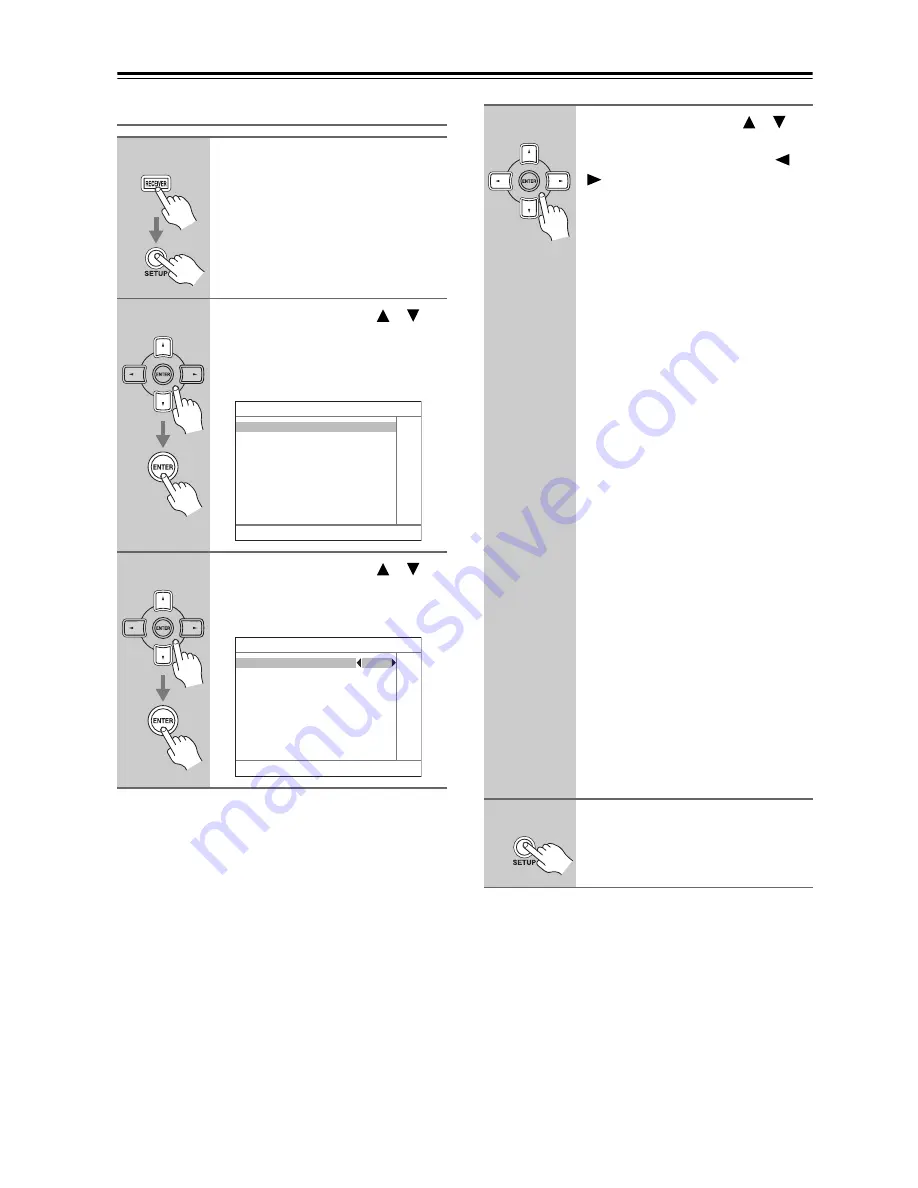
1

Press the [RECEIVER] button fol-
lowed by the [SETUP] button.

The main menu appears onscreen.

2

Use the Up and Down [

]/[

buttons to select 
“6. Miscellaneous,” and then 
press [ENTER].

The Miscellaneous menu appears.

3

Use the Up and Down [

]/[

buttons to select “2. OSD Setup,” 
and then press [ENTER].

The OSD Setup menu appears.

6. Miscellaneous

1. Volume Setup
2. OSD Setup

6–2. OSD Setup

Immediate Display 

On

Monitor Type 

4 : 3

Display Position 

Bottom

TV Format 

Auto

4

Use the Up and Down [

]/[

buttons to select the settings, 
and use the Left and Right [

]/

[

] buttons to set them.

These settings determine how the oper-
ation details are displayed.

Immediate Display

This preference determines whether 
operation details are displayed 
onscreen when an AV receiver/AV 
amplifier function is adjusted.

On:

Displayed (default).

Off:

Not displayed.

Even when On is selected, operation 
details are not output if the input source 
is connected to a COMPONENT 
VIDEO IN or HDMI IN.

Monitor Type

With this preference, you can specify 
the aspect ratio of your TV so that the 
operation details are displayed prop-
erly.

4 : 3:

Select if your TV is 4 : 3 
(default).

16 : 9:

Select if your TV is 16 : 9.

Display Position

This preference determines where on 
the screen operation details are dis-
played.

Bottom:

Bottom of the screen 
(default).

Top:

Top of the screen.

TV Format (not North American 

models) 

See “TV Format Setup (not North 
American models)” on page 52.

5

When you’ve finished, press the 
[SETUP] button.

The setup menu closes.

Summary of Contents for SR605S - AV Receiver

Page 1: ...in the unit Following the instructions in this manual will enable you to obtain optimum performance and listening enjoyment from your new AV Receiver AVAmplifier Please retain this manual for future r...

Page 2: ...aratus does not operate normally by following the operating instructions Adjust only those controls that are covered by the operating instructions as an improper adjustment of other controls may resul...

Page 3: ...s unit for a long time because they may leave marks on the case This unit s top and rear panels may get warm after prolonged use This is normal If you do not use this unit for a long time it may not w...

Page 4: ...Specifications and operations are the same regardless of color Declaration of Conformity We ONKYO EUROPE ELECTRONICS GmbH LIEGNITZERSTRASSE 6 82194 GROEBENZELL GERMANY GROEBENZELL GERMANY ONKYO EUROPE...

Page 5: ...for iPod Aluminum Front Panel Preprogrammed RI Compatible Remote 1 Manufactured under license from Dolby Laboratories Dolby Pro Logic and the double D symbol are registered trademarks of Dolby Labora...

Page 6: ...al Input Setup 50 Changing the Input Display 51 Speaker Settings 51 TV Format Setup not North American models 52 AM Frequency Step Setup on some models 53 Basic Operations Basic Operations 54 Selectin...

Page 7: ...le a signal is being received from the remote controller ZONE 2 indicator 88 This indicator lights up when Zone 2 is selected Remote control sensor 12 This sensor receives control signals from the rem...

Page 8: ...is used to display various information about the currently selected input source 7 DIGITAL INPUT button 50 85 This button is used to assign the digital inputs and to specify the format of digital inpu...

Page 9: ...STEREO 57 This indicator lights up when the AV receiver is tuned to a stereo FM station RDS European models only 59 This indi cator lights up when tuned to a radio station that supports RDS Radio Data...

Page 10: ...h American model TX SR605 other than North American model TX SA605 8560 Rear Panel bn bp br bt ck cl bo bq bl 1 23 8 5 6 9 7 4 bm bs bn bt ck cl 1 8 5 6 9 7 bk 4 bp br bs bo bq bl bm Only some models...

Page 11: ...d to an jack on another Onkyo AV compo nent The AV receiver AV amplifier s remote controller can then be used to control that compo nent To use you must make an analog audio connection RCA between the...

Page 12: ...the same room or the AV receiver AV amplifier is installed close to equipment that uses infrared rays the remote controller may not work reliably Don t put anything such as a book on the remote con tr...

Page 13: ...ge 90 TV VCR and SAT CABLE Modes With these modes you can control a TV VCR and satellite or cable receiver You must enter the appropriate remote control code first see page 90 Note Some of the remote...

Page 14: ...er button is pressed the REMOTE MODE button for the currently selected mode lights up 3 SLEEP button 56 Used with the Sleep function 4 VOL button 54 Adjusts the volume of the AV receiver AV amplifier...

Page 15: ...s AUDIO button Selects foreign language soundtracks and audio for mats e g Dolby Digital or DTS 1 DISPLAY button Displays information about the current disc title chapter or track including elapsed ti...

Page 16: ...recorder including elapsed time remaining time total time and so on On an HDD compatible component connected to an RI Dock it turns on the back light for 30 seconds CLR button Cancels functions and c...

Page 17: ...The subwoofer handles the bass sounds of the LFE Low Frequency Effects channel The volume and quality of the bass output from your subwoofer will depend on its position the shape of your listening roo...

Page 18: ...ght red Yellow Analog audio Composite video Left white Right red Yellow Right Wrong Video Cable Jack Description Component video cable Component video separates the luminance Y and color difference si...

Page 19: ...ofer is unpowered and you re using an external amplifier con nect the PRE OUT SUBWOOFER to an input on the amp Attaching the Speaker Labels The AV receiver AV amplifier s positive speaker ter minals a...

Page 20: ...the sound will be out of phase and will sound unnatural Unnecessarily long or very thin speaker cables may affect the sound quality and should be avoided If you use 4 or 5 speakers connect each of th...

Page 21: ...igher for bi amping Failure to do so may seriously damage the AV receiver AV amplifier Bi amping Speaker Hookup Bi amping the Front Speakers 1 Connect the AV receiver AV amplifier s FRONT R positive t...

Page 22: ...s Once your AV receiver is ready for use you ll need to tune into an FM radio station and adjust the position of the FM antenna to achieve the best possible reception 2 Use thumbtacks or something sim...

Page 23: ...tenna must be grounded in accordance with local regulations to prevent electrical shock haz ards Using a TV FM Antenna Splitter It s best not to use the same antenna for both FM and TV reception as th...

Page 24: ...he best picture quality The AV receiver AV amplifier can upconvert and downconvert between video formats depending on the HDMI Monitor setting which generally determines whether video signals are upco...

Page 25: ...HDMI outputs pass through their respective input signals as they are Audio Connection Formats Audio equipment can be connected to the AV receiver AV amplifier by using any of the follow ing audio con...

Page 26: ...ow TV Picture quality COMPONENT VIDEO OUT Component video input Best MONITOR OUT S S Video input Better MONITOR OUT V Composite video input Standard GAME TV IN L R Analog audio L R output DIGITAL COAX...

Page 27: ...ard DVD IN FRONT L R Analog audio L R output DIGITAL COAXIAL IN 1 DVD Digital coaxial output DIGITAL OPTICAL IN 1 GAME TV Digital optical output Step 1 Video Connection Choose a video connection that...

Page 28: ...a multichannel analog audio cable or several normal audio cables to connect the AV receiver AV amplifier s DVD IN FRONT L R CENTER SURR L R SURR BACK L R and SUBWOOFER jacks to the 7 1 channel analog...

Page 29: ...r to your TV via the same type of connection A B C Step 2 Audio Connection Choose an audio connection that matches your VCR or DVD recorder or and then make the connection a b c a b c a b a c Connecti...

Page 30: ...be connected to a composite video output Similarly video signals connected to S Video inputs can only be recorded via S Video outputs If your TV VCR is connected to an S Video input the recording VCR...

Page 31: ...o output Better CBL SAT IN V Composite video output Standard CBL SAT IN L R Analog audio L R output DIGITAL COAXIAL IN 2 CBL SAT Digital coaxial output DIGITAL OPTICAL IN 1 GAME TV Digital optical out...

Page 32: ...ut Better GAME TV IN V Composite video output Standard GAME TV IN L R Analog audio L R output DIGITAL OPTICAL IN 1 GAME TV Digital optical input Step 1 Video Connection Choose a video connection that...

Page 33: ...R Analog audio L R output AUX INPUT DIGITAL Digital optical output Step 1 Video Connection Choose a video connection that matches the camcorder or and then make the connection A B Step 2 Audio Connec...

Page 34: ...ion Audio DTS HD Master Audio Your DVD player must also support HDMI output of the above audio formats About Copyright Protection The AV receiver AV amplifier supports HDCP High bandwidth Digital Cont...

Page 35: ...g to an HDMI component through the AV receiver AV amplifier set the HDMI component so that its video can be seen on the TV screen on the TV select the input of the HDMI component connected to the AV r...

Page 36: ...ble Connection AV receiver AV amplifier Signal flow CD or turntable CD IN L R Analog audio L R output DIGITAL COAXIAL IN 2 CBL SAT Digital coaxial output DIGITAL OPTICAL IN 2 CD Digital optical output...

Page 37: ...with the DS A1 RI Dock without video Connect your RI Dock s analog audio output jacks to the AV receiver AV amplifier s TAPE IN L R jacks Connecting an RI Dock AUDIO OUT L R S VIDEO OUT AUDIO OUT L R...

Page 38: ...input DIGITAL COAXIAL IN 2 CBL SAT Digital coaxial output DIGITAL OPTICAL IN 1 GAME TV Digital optical output Connecting a Tuner TX SA605 8560 only COAXIAL OUT AUDIO IN L R OPTICAL OUT L R IN TAPE AU...

Page 39: ...ontrol your other capable Onkyo components pointing the remote controller at the AV receiver AV amplifier s remote control sensor instead of the component You must enter the appro priate remote contro...

Page 40: ...the STANDBY ON button or press the remote controller s STANDBY ON button The AV receiver AV amplifier will enter Standby mode To prevent any loud surprises when you turn on the AV receiver AV amplifie...

Page 41: ...ng position if it s just one person Second measurement point The right side of the listening area Third measurement point The left side of the listening area The distances between points and and point...

Page 42: ...not work correctly so don t make any noise Auto Speaker Setup AUDYSSEY Please place microphone at center of listening area at ear height Push Enter Next Auto Speaker Setup AUDYSSEY Do not unplug micr...

Page 43: ...Push Enter Next Auto Speaker Setup AUDYSSEY Calculating 8 When the calculations are com plete the following screen appears Use the Up and Down buttons to select an option and then press ENTER The opti...

Page 44: ...first measurement Make sure speakers that cannot be detected are con nected property Retry Return to step 2 and try again Cancel Cancel the automatic speaker setup Write Error This message appears if...

Page 45: ...an appropriate vol ume level If the subwoofer has a low pass filter switch set it to Off or Direct Refer to your subwoofer s instruc tion manual for details Use the Up and Down buttons to select the s...

Page 46: ...ital Input 2 Speaker Setup 1 Speaker Settings 2 Speaker Config 3 Speaker Distance 4 Level Calibration 5 Equalizer Settings 3 Audio Adjust 1 Tone Control 2 Multiplex Mono 3 PLIIx Neo 6 4 Dolby EX 5 The...

Page 47: ...tton HDMI Monitor 1 5 2 4 2 3 1 IN OUT Composite video S Video Composite video S Video Component video Component video IN OUT Composite video S Video component video Composite video S Video component...

Page 48: ...See Digital Input Setup on page 50 This procedure can also be performed on the AV receiver AV amplifier by using its SETUP button arrow buttons and ENTER button Video Input Setup 1 Press the RECEIVER...

Page 49: ...by using its SETUP button arrow buttons and ENTER button Input selector VIDEO IN jack DVD IN 1 VCR DVR CBL SAT GAME TV AUX 1 Press the RECEIVER button fol lowed by the SETUP button The main menu appea...

Page 50: ...lowed by the SETUP button The main menu appears onscreen 2 Use the Up and Down buttons to select 1 Input Out put Assign and then press ENTER The Input Output Assign menu appears 3 Use the Up and Down...

Page 51: ...eakers in the main room Before you change these settings turn down the vol ume Changing the Input Display 1 Press the TAPE or GAME TV input selector button so that TAPE or GAME TV appears on the displ...

Page 52: ...rs normally Bi Amp Select this if you ve con nected your front speakers for bi amped operation 6 Press the SETUP button The Setup menu closes TV Format Setup not North American models 1 Press the RECE...

Page 53: ...ollowed by the SETUP button The main menu appears onscreen 2 Use the Up and Down buttons to select 7 Hardware Setup and then press ENTER The Hardware Setup menu appears 3 Use the Up and Down buttons t...

Page 54: ...omponent When you select DVD or another video component on your TV you ll need to select the video input that s connected to the AV receiver AV amplifier s COMPONENT VIDEO OUT HDMI OUT or MONITOR OUT...

Page 55: ...This procedure can also be performed on the AV receiver AV amplifier by using its DISPLAY button The following information can typically be displayed for input sources If the input signal is analog n...

Page 56: ...with headphones the listening modes available also depend on the currently selected input source When the multichannel input is used only the front left and right audio can be heard in the headphones...

Page 57: ...enter ing the appropriate frequency Using the Tuner Use the TUNER input selector button to select either AM or FM In this example FM has been selected Each time you press the TUNER but ton the input s...

Page 58: ...nds use the PRESET buttons to select a preset from 1 through 40 4 Press the MEMORY button again to store the station or channel The station or channel is stored and the preset number stops flashing Re...

Page 59: ...radio stations by type see page 60 TP Traffic Program This allows you to search for RDS radio stations that broadcast traffic information see page 60 Notes In some cases the text characters displayed...

Page 60: ...ESET buttons to select the type of program you want See the table on page 59 RT PTY TP 2 4 5 1 3 4 To start the search press ENTER The AV receiver searches until it finds a station of the type you spe...

Page 61: ...the listening modes that can be used with the cur rent input source Selecting with the Remote Controller SURROUND button This button selects the Dolby Digital and DTS listen ing modes and the Neural S...

Page 62: ...Not available while Powered Zone 2 is being used Listening Modes Available for Each Source Format Source format PCM Multichannel PCM 32 192 kHz 32 96 kHz 176 4 192 kHz 1 Multichannel 1 0 1 1 Media Lis...

Page 63: ...t available while Powered Zone 2 is being used Source format Dolby D Dolby Digital Plus TrueHD 1 Multichannel 2ch 1 0 1 1 Multichannel 2ch 1 0 1 1 Multi channel 2ch 1 0 1 1 2 except 2 2 except 2 Media...

Page 64: ...one 2 is being used Source format DTS DTS 96 24 DTS Discrete Matrix Multichannel 2ch 1 0 2 except 2 Media Listening mode DVD CD etc DVD CD etc Pure Audio not North American models Direct Stereo Multic...

Page 65: ...used Requires 7 1 speakers Not available while Powered Zone 2 is being used Source format DTS HD High Resolution Audio DTS HD Master Audio 1 Multichannel 2ch 1 0 Multi channel 2ch 1 0 2 except 2 Medi...

Page 66: ...rt hall 5 1 channel source Dolby EX These modes expand 5 1 channel sources for 6 1 7 1 channel playback They re especially suited to Dolby EX soundtracks that include a matrix encoded surround back ch...

Page 67: ...round employs psychoacoustic frequency domain processing which allows delivery of a more detailed sound stage with superior channel separation and localization of audio elements System playback is sca...

Page 68: ...24 to 39 for hookup information Recording Separate AV Sources Here you can record audio and video from completely separate sources allowing you to overdub audio onto your video recordings This functio...

Page 69: ...otes You cannot use this function while the AV receiver AV amplifier is muted Speakers that are set to No or None in the Speaker Configuration cannot be adjusted Using the Late Night Function Dolby Di...

Page 70: ...peaker s manuals to determine the optimum crossover frequencies Speaker Setup This setting is set automatically by the Automatic Speaker Setup function see page 41 2 11 2 3 1 1 12 1 Press the RECEIVER...

Page 71: ...in step 5 is set to anything other than Full Band Full Band cannot be selected here 8 Use the Up and Down buttons to select Surr Back and then use the Left and Right buttons to select a crossover freq...

Page 72: ...select 2 Speaker Setup and then press ENTER The Speaker Setup menu appears This setting is set automatically by the Automatic Speaker Setup function see page 41 2 6 2 3 1 1 7 2 Speaker Setup 1 Speaker...

Page 73: ...elect 2 Speaker Setup and then press ENTER The Speaker Setup menu appears This setting is set automatically by the Automatic Speaker Setup function see page 41 1 6 2 5 2 3 1 2 Speaker Setup 1 Speaker...

Page 74: ...o select Off Tone off response flat Audyssey The tone for each speaker is set automatically by the Automatic Speaker Setup function Be sure to select this set ting after having per formed the Automati...

Page 75: ...by using its SETUP button arrow buttons and ENTER button 7 Use the Up button to select Channel and then use the Left and Right buttons to select another speaker Repeat step 6 and 7 for each speaker 8...

Page 76: ...TV broadcasts and so on Main The main channel is output default Sub The sub channel is output Main Sub Both the main and sub channels are output Mono Input Ch This setting specifies the channel to be...

Page 77: ...e adjusted from 0 to 7 default is 3 Center Image The DTS Neo 6 Music listening mode creates 6 channel surround sound from 2 channel stereo sources With this setting you can specify by how much the fro...

Page 78: ...elect a listening mode Only listening modes that can be used with each input signal format can be selected The Last Valid option means that the listening mode selected last will be used Analog PCM Wit...

Page 79: ...VER button fol lowed by the SETUP button The main menu appears onscreen 1 3 1 6 2 4 5 2 4 2 Use the Up and Down buttons to select 4 Source Setup and then press ENTER The Source Setup menu appears 3 Us...

Page 80: ...Source Setup and then press ENTER The Source Setup menu appears 3 Use the INPUT SELECTOR but tons on the remote controller to select the input source that you want to correct This can be the DVD VCR...

Page 81: ...to select the settings and use the Left and Right buttons to set them Maximum Volume With this preference you can prevent the volume being set too high by speci fying a maximum volume level The range...

Page 82: ...m These settings determine how the oper ation details are displayed Immediate Display This preference determines whether operation details are displayed onscreen when an AV receiver AV amplifier funct...

Page 83: ...nkyo component located in the same room If you change the AV receiver AV amplifier s remote control ID be sure to set the same ID on both the AV receiver AV amplifier and remote con troller see page 8...

Page 84: ...be operated together with the AV receiver AV amplifier Disable HDMI Control disabled Enable HDMI Control enabled Notes Set to Disable when a connected piece of equipment is not compatible or it is un...

Page 85: ...enu appears onscreen 2 Use the Up and Down buttons to select 8 Lock Setup and then press ENTER The Lock Setup menu appears With this preference you can protect your settings by locking the setup menus...

Page 86: ...te If you change the remote controller s ID be sure to set the same ID on both the remote controller and AV receiver AV amplifier see Changing the AV Receiver AV Amplifier s ID on page 83 The default...

Page 87: ...erminals on the receiver integrated amp Using Only Speakers in Zone 2 With this connection method you can use 5 1 surround sound in the main room and play a different AV source in Zone 2 The volume fo...

Page 88: ...t and Right buttons to select Not Act ZONE 2 SPEAKERS termi nals deactivated Act ZONE 2 SPEAKERS termi nals activated When Zone 2 is activated and turned on see below the speakers connected to the ZON...

Page 89: ...2 is on functions will not work You can t select different radio stations for Zone 2 and the main room For example if you have an FM sta tion for the main room that station will also be used in Zone 2...

Page 90: ...rect at the time of printing but are subject to change Entering Remote Control Codes 1 Look up the appropriate remote control code in the separate Remote Control Codes list The codes are organized by...

Page 91: ...mponent is con nected with an cable and an analog audio cable RCA See page 39 for details 2 Enter the appropriate remote control code for the DVD or CD REMOTE MODE but ton DVD REMOTE MODE button 1612...

Page 92: ...marked with an aster isk are exclusively for con trolling a TV and can be used at anytime regardless of the cur rent remote controller mode Controlling a VCR STANDBY ON Sets the VCR to Standby or On N...

Page 93: ...Hz BASS 10 dB 20 kHz TREBLE Signal to Noise Ratio 100 dB LINE IHF A Speaker Impedance North American 6 16 Others 4 or 6 16 Input Sensitivity Output Level and Impedance 1 Vp p 75 Component and S Video...

Page 94: ...consoles such as those that support DVD the default setting is off With some DVD Video discs you need to select an audio output format from a menu If your turntable doesn t have a built in phono pream...

Page 95: ...eHD page 69 The DVD analog multichannel input doesn t work Check the DVD analog multichannel input connec tions page 28 To select the DVD analog multichannel input press the MULTI CH input selector bu...

Page 96: ...aken radio signals If nothing improves the reception install an outdoor antenna The remote controller doesn t work Make sure that the batteries are installed with the cor rect polarity page 12 Install...

Page 97: ...n nected via These functions don t work when Zone 2 is turned on When performing Automatic Speaker Setup the measurement fails showing the message Ambient noise is too high This can be caused by any m...

Page 98: ...98 MEMO...

Page 99: ...99 MEMO...

Page 100: ...oebenzell GERMANY Tel 49 8142 4401 0 Fax 49 8142 4401 555 http www eu onkyo com ONKYO EUROPE UK Office Suite 1 Gregories Court Gregories Road Beaconsfield Buckinghamshire HP9 1HQ UNITED KINGDOM Tel 44...

Reviews: