background image


29733 R2  06/01/2003


7

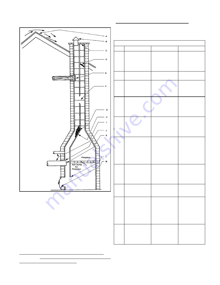
Figure 2: Common Chimney Problems 

6.  CHIMNEY VENTING 

The chimney must be sized correctly and be in good 
repair. If the chimney is oversized, there is a high risk of 
the flue gases condensing resulting in damage to the 
chimney and other venting parts. This problem may be 
corrected by the use of an appropriately sized chimney 
liner. 
 
If the chimney serves the furnace only, the vent should 
be sized at 4 inch minimum, 5 inch maximum. The table 
below is based on dedicated venting. If the furnace is to 
be co-vented with other appliances, refer to 

NFPA 31

Standard for the Installation of Oil Burning Equipment

 and 

NFPA 211

Standard for Chimneys, Fireplaces, Vents, 

and Solid Fuel-Burning Appliances

 or 

CAN/CSA B139

Installation Code For Oil Burning Equipment

 for correct 

sizing information 
 

Table 3: Common Chimney Problems


Refer to Figure 2 

Key Trouble  Diagnostic  Remedy 

Top of chimney 
lower than 
surrounding  
objects 

Observation 

Extend 
chimney above 
all surrounding 
objects within 
30 feet. 

Chimney Cap 
or ventilator. 

Observation Remove 

Coping restricts 
opening. 

Observation 

Make opening 
as large as 
inside of 
chimney. 

Obstruction in 
chimney  


Can be found  
by light and 
mirror reflecting 
conditions in 
chimney. 

Use weight to  
break and 
dislodge. 

Joist protruding 
into chimney. 

Lowering a light 
on an extension 
cord. 

Must be 
handled by 
competent 
masonry 
contractor. 

Break in 
chimney lining. 

Smoke test - 
build smudge 
fire blocking off 
other opening, 
watching for 
smoke to 
escape. 

Must be 
handled by 
competent 
masonry 
contractor. 

Collection of 
soot at narrow 
space in flue 
opening. 

Lower light on 
extension cord. 

Clean out with 
weighted brush 
or bag of loose 
gravel on end 
of line. 

H Offset 

Lower light on 
extension cord. 

Change to 
straight or to 
long offset. 

Two or more 
openings to the 
same chimney. 

Found by 
inspection from 
basement. 

The least 
important 
opening must 
be closed, 
using some 
other chimney 
flue. 

Loose-seated 
pipe in flue 
opening. 

Smoke test. 

Leaks should 
be eliminated 
by cementing 
all pipe 
openings. 


Summary of Contents for Air Furnace

Page 1: ...REGULATION OF AUTHORITIES HAVING JURISDICTION AND NFPA STANDARD 31 U S A OR CSA STANDARD B139 CAN FOR YOUR SAFETY Do not store or use gasoline or other flammable vapors or liquids in the vicinity of t...

Page 2: ...e Beckett Oil Burner 4 tons of cooling Highboy 2 nd Generation Heat Exchanger Nominal Output BTUH 80 Compact Highboy 120 Standard Highboy Breech Location F Front Cooling Airflow 3 3 Tons 4 4 Tons 5 5...

Page 3: ...n Set Up 16 21 Operating Instructions 17 Table A 1 Beckett AF Oil Burner Set Up 18 Table A 2 Riello 40F Oil Burner Set Up 18 Table A 3 Direct Drive Blower Set Up 19 Table A 4 Direct Drive Blower Chara...

Page 4: ...ecedence over the general instructions provided with this installation manual When in doubt please consult your local authorities All models are shipped assembled and pre wired The furnace should be c...

Page 5: ...arging right by following these steps 1 Rotate the furnace 90 to the desired position 2 Remove the three nut and washer sets fastening the oil burner assembly to the furnace Beckett Burner or loosen t...

Page 6: ...t be a means of control to prevent the operation of either system unless the dampers are in the full heat or full cool position The air heated by the furnace shall not pass through a refrigeration uni...

Page 7: ...surrounding objects Observation Extend chimney above all surrounding objects within 30 feet B Chimney Cap or ventilator Observation Remove C Coping restricts opening Observation Make opening as large...

Page 8: ...e chimney at a rate of one quarter inch to the foot The flue pipe should not be smaller in cross sectional area than the flue collar on the furnace The flue pipe should connect to the chimney such tha...

Page 9: ...rotected against over heating by fixed high temperature limits These controls are factory set and are not field adjustable If an over temperature condition is detected one or both limit switches will...

Page 10: ...on should be carried out in accordance with the humidifier manufacturer s installation instructions Water or water droplets from the humidifier should not be allowed to come into contact with the furn...

Page 11: ...0 230 9 5 25 100 11 20 65 For additional information see the installation information sheet included in the documents envelope or affixed to the oil burner NOTE Both the Beckett and Riello oil burners...

Page 12: ...ctrode porcelains should be free of cracks the electrode tips should be tapered and free of burrs and the contact rods must be clean and be in firm contact with the ignition transformer contact spring...

Page 13: ...a sign of unburned fuel This indicates poor combustion This type of problem may be caused by excess draft excess air or contaminated fuel Do not ignore this indicator STACK TEMPERATURE Stack temperatu...

Page 14: ...odating both wires on a single motor tap It is also acceptable to connect the selected motor speed with a pigtail joined to both heating and cooling speed wires with a wire nut As a safety precaution...

Page 15: ...ntly high voltages to damage accessory equipment Use the terminals provided on the ST9103 EFT DO NOT START THE BURNER OR BLOWER FAN UNLESS THE BLOWER ACCESS DOOR IS SECURELY IN PLACE Additional ST9103...

Page 16: ...ly air and return air temperatures when the furnace has reached steady state conditions This is the point at which the supply air temperature stops increasing relative to the return air temperature Th...

Page 17: ...to start the furnace during these conditions and who to call for emergency service 21 OPERATING INSTRUCTIONS Before Lighting Open all supply and return air registers and grilles Open all valves in oi...

Page 18: ...United States the R W Beckett AFG Burner may be equipped with Beckett s Inlet Air Shut Off Beckett Part No AF A 5861 to increase efficiency It reduces the amount of air passing through the oil burner...

Page 19: ...on temperature rise Upper values may exceed measured airflow values in Table A 3 2 Nominal Values Only TABLE A 4 DIRECT DRIVE BLOWER CHARACTERISTICS CFM External Static Pressure inches w c Furnace Mo...

Page 20: ...TERISTICS CFM External Static Pressure inches w c Furnace Model Motor hp Blower Temp Rise DT Motor FLA Motor Pulley Turns Out 0 20 0 30 0 40 0 50 0 60 0 70 0 1596 1518 1435 1330 1247 1184 1 1505 1434...

Page 21: ...ons inches Plenum Openings Cabinet Supply Air Return Air Flue Width A Depth B Height C D x E Side F x G Bottom Dia Height H Filter Perm Ship Weight lb 80F 22 31 49 20 x 20 14 x 22 14 x 22 5 42 16 x 25...

Page 22: ...29733 R2 06 01 2003 22 WIRING DIAGRAM OIL FURNACE WITH ST9103 EFT R7184 CONTROL Appendix B WIRING...

Page 23: ...29733 R2 06 01 2003 23 WIRING DIAGRAM OIL FURNACE WITH ST9103 EFT RIELLO OIL BURNER Appendix B WIRING...

Page 24: ...well as 115 volts to a line voltage humidifier or humidifier step down transformer Both sets of terminals are inch quick connect type rated at 1 A each The EAC terminals provide power to an electronic...

Page 25: ...rk for 10 sec a Provides continuous spark after flame is sensed to assure that burner remains lit b Turns on LED diagnostic light c Starts carryover timer i Flame and call for heat are monitored If fl...

Page 26: ...TAT SATISFIED R7184 SHUTS OFF Burner Motor Solenoid Valve LED Diagnostic Light RETURNS TO IDLE STATE FLAME FLAME FLAME FLAME NO FLAME NO FLAME FLAME LOST FLAME LOST REMAINS IN IDLE STATE R7184 SEQUENC...

Page 27: ...good contact between control box spades and sub base terminals Defective control box Replace Verify electrical connections Check for seized pump motor or fan against housing Defective motor capacitor...

Page 28: ...alve closed dirty filter damaged supply lines Defective or dirty oil valve stem nozzle or pump strainer Broken pump drive key defective pump no oil pressure Ignition electrodes shorted cracked porcela...

Page 29: ...seconds b Burner motor is de energized even though thermostat is still calling for heat c If circulator fan has started it continues through the selected heat fan off delay period Established flame f...

Page 30: ...call for heat a Circulator fan turns off when heat fan off delay time is complete b Normal operation resumes ST9103 control is in standby mode awaiting next thermostat command FAN Continuous circulati...

Page 31: ...flame or viewing ambient light The resistance of the cad cell may be checked while the R7184 is in the run state by pressing the reset button The LED diagnostic light will flash the following code TA...

Page 32: ...n there is a call for heat Procedure Status Corrective Action 1 Check that limit switches are closed and contacts are clean This includes the burner motor reset button N A N A 2 Check for line voltage...

Page 33: ...ndicator light flashing at 1 Hz rate second on second off Procedure Status Corrective Action 1 Check that the limit switches are closed and contacts are clean 2 Check for line voltage power at the oil...

Page 34: ...by pushing in and releasing red reset button Indicator light continues to flash at 1 Hz rate Verify that the control is not in restricted mode See notes at end of this table If not in restricted mode...

Page 35: ...n socket Reconnect line voltage power and close line switch Start burner Burner keeps running System is OK Indicator light is on Remount control onto burner housing Go to step 6 10 Check cad cell Disc...

Page 36: ...ND GENERAL TROUBLESHOOTING Problem Possible Cause Remedy Thermostat not calling for heat Check thermostat and adjust Also check thermostat for accuracy if it is a mercury switch type it might be off l...

Page 37: ...l is getting dirty If cad cell is poorly aimed realign it NOTE The photocell should have a resistance of 100K W in absence of light a maximum of 1500 W in the presence of light Ensure that room light...

Page 38: ...ose as possible to this fan off temperature Fuel oil leak Check fuel oil line for leaks Repair or replace if necessary Stack temperature too high Check stack temperature Stack temperatures will normal...

Page 39: ...an motor amperage draw Check motor ventilation ports clean if necessary Replace motor if necessary Furnace will not warm home to desired temperature Burner motor stopping intermittently on overload Ch...

Page 40: ...or Contact Address Postal Code Telephone No After Hours No Service Contractor if different from Installation Contractor Service Tech Telephone No After Hours No Fuel Supplier Oil Supplier Contact Tele...

Reviews: