background image

www.onbonbx.com

第 18 页

Note

Regardless of whether the input image ratio is 4:3 or 16:9, the output

image is displayed by "full screen" by default, so in some cases it will cause

equal proportion distortion of people, at this time, you can change the width

and height of the image through "display window adjustment" ratio.

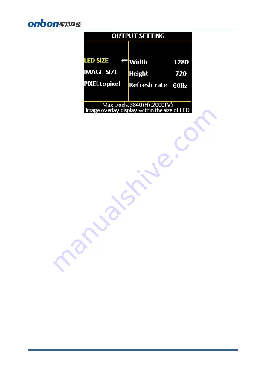
2. Pixel to pixel

In the non-menu state, click the [OK] button to enter the main menu, then

select "Output Settings", and then select "Point-to-point output" to enter the

point-to-point output menu.The default state of point-to-point output is off.

When the point-to-point output is in the "on" state, the input signal is

directly output to the output without any processing by the processor, that

is, the output image and the input image are completely point-to-point.

note:

(1) When the point-to-point output is in the "on" state, the controller

outputs the input image to the large LED screen without any scaling at this

time.Therefore, it is very convenient to debug the LED screen module (plot

point display, etc.);

(2) The point-to-point output is only valid in the range of 3840*2160;

(3) When the input resolution is set to the same size as the LED through

the "Advanced Options-Input Resolution" menu, the image can be

displayed without any scaling, so the best display effect can be achieved.

(4) When the point-to-point output is turned on, the image capture will be

automatically turned off.

Image quality

Click

OK

as to enter into main menu--”IMAGE QUALITY”, as below:

Summary of Contents for OVP-H4D

Page 1: ...USER MANUAL OVP H4D Version V1 1 Date 2019 7 23...

Page 2: ...his file without our written permission And cannot use it on any business or benefit filed with any forms The specifications and information which are mentioned on the file is for reference only if th...

Page 3: ...3 Instruction 5 Safety notification 5 Functions 6 Description 6 Features 6 PANEL 7 Front panel 7 Basic steps 9 Menu 9 Menu button operation 9 The initial state of the main interface 10 Main menu 10 S...

Page 4: ...www onbonbx com 4 Image quality 18 Crop menu 19 Option 20 USER SAVE AND LOAD MODE 24 User save mode 24 User mode switch 25 MODE 26 FAST MODE 26 Intelligent guiding 27 FAQ 28 Technical parameters 30...

Page 5: ...onductor in the power cord is essential for safe operation Before performing any hardware operations please turn off the power of the LED video processor and discharge static electricity on your body...

Page 6: ...imum8000 pixels vertical maximum 3840 pixels Fast seamless switching between all input signal sources and output modes With 7 channels of ultra high definition UHD digital and analog input interface D...

Page 7: ...www onbonbx com 7 PANEL Front panel...

Page 8: ...www onbonbx com 8...

Page 9: ...ove four steps please refer to the next chapter Introduction to Main Menu Menu Menu button operation The key operation area related to the menu is the MENU area including a knob a confirmation key OK...

Page 10: ...e of the main interface During the system start up the LCD screen will display the startup interface After the startup is complete the current machine status will be displayed on the screen The initia...

Page 11: ...tical maximum 3840 Horizontal splice maximum 8000 vertical maximum 2000 LAYOUT Picture 1 horizontal width vertical height horizontal start vertical start is always on Picture 2 picture switch horizont...

Page 12: ...Factory reset ADC calibration languages factory reset firmware version Splice mode The system provides two splicing methods for users to choose As mentioned above you need to select the splicing meth...

Page 13: ...ber of points cannot exceed 5 1 million points For details see The setting instructions of LED screen parameter will follow This splicing method is more suitable for the screen with long shape Vertica...

Page 14: ...please refer to the setting instructions of LED screen parameter below The splicing method is more suitable for the ultra high definition LED large screen in the shape of a vertical bar LED screen par...

Page 15: ...tal width of the LED screen 4096 LED screen total height 2000 Value range of OUT1 OUT2 output port Width 0 4000 height 0 2000 Note When the width and height of an output port in OUT1 OUT4 is 0 it mean...

Page 16: ...m value is the maximum number of horizontal points minus the horizontal width Vertical start The minimum value is 0 and the maximum value is the maximum number of vertical points minus the vertical he...

Page 17: ...synchronously so generally no need to set the LED screen parameters Including the size of the LED screen and the parameters of each network port 2 When you need to arbitrarily splice or set for each...

Page 18: ...ctly output to the output without any processing by the processor that is the output image and the input image are completely point to point note 1 When the point to point output is in the on state th...

Page 19: ...Dynamic contrast adjust range 0 4 default is 1 0 means closed it s invalid for inputting VGA signal source Color temperature warm natural cold custom Customized color temperature adjusting range in RE...

Page 20: ...source 2 Users can select different input source by input source button on boar Option Click OK as to enter into main menu OPTION as below 1 Input EDID It offers EDID editing function of DVI HDMI inp...

Page 21: ...plicing method interface type and input bandwidth limitation For this device because the standard used by the system s input sources DP1 and DP2 is DP1 2 the highest level of input resolution can be a...

Page 22: ...m 2 When there s excursion of VGA input signal in display users can click Auto adjust as to display correctly And if Auto adjust is invalid users can adjust VGA horizontal start and VGA vertical start...

Page 23: ...re are four adjustment items in Other Settings Switching special effects including seamless fast cut and fade in and fade out two special effects Sound settings including audio switch and volume setti...

Page 24: ...ne before selling in our factory Language Chinese and English default is Chinese Factory reset Reset to default value Firmware version Check present hardware version factory date USER SAVE AND LOAD MO...

Page 25: ...t the currently selected mode data does not exist 3 Up to 8 user modes can be saved In addition to the size position and status of the screen the parameters saved in the user mode also include brightn...

Page 26: ...MODE to the fix mode calling Move the cursor to the corresponding mode and press OK to call the corresponding system fixed mode Description 1 From single picture to four picture system a total of 4 fi...

Page 27: ...ource in this monitoring window When the pre monitoring source is stable and correct press the TAKE button to instantly switch the pre monitoring source to the current playback window This function is...

Page 28: ...display or image output in LCD screen Please check power supply cable Please check ON OFF button of power supply There s display on LCD screen but do not have image output Please check that it is con...

Page 29: ...not in middle Continuously press AUTO button on board until it shows correctly When you do auto adjust please use full screen without black frame signal Image is in middle but there s black frame This...

Page 30: ...www onbonbx com 30 Technical parameters...

Page 31: ...ty China ONBON Jiangsu Optoelectronic Industrial Co LTD Address 1299 Fuchun Jiang Road Kunshan City Jiangsu Province China Tel Phone 086 0512 36912687 Website www onbonbx com Sales Contacts Tel 0086 1...

Reviews: