4-7
Always use flexible tubing between en-
gine and the fuel supply to avoid line failure due to
vibration.
Never use galvanized or copper fuel
lines, fittings or fuel tanks with diesel fuel systems.
Condensation in the tank and lines combines with
the sulfur in diesel fuel to produce sulfuric acid. The
molecular structure of the copper or galvanized lines
or tanks reacts with the acid and contaminates the
fuel.
Carefully clean all fuel system components before put-
ting the set into operation. Any dirt or contamination may
cause major damage to the fuel injection system.
Dirt in the system can severely damage
both the injection pump and the injection nozzles.
Dirty fuel is one of the major causes of engine failure.
Even a tiny particle of dirt in the injection system may
stop the engine. Because diesel injection systems
have extremely precise tolerances, make certain that
fuel is kept clean.
Separate Fuel Tanks
The fuel tank top must be lower than the fuel pump level
to prevent putting a static head on the fuel pump inlet. If
the fuel tank is shared with another engine, use separate
fuel lines for both engines to avoid starving either one.
The following restrictions apply to separate fuel tank in-
stallation:
1. The bottom of the fuel tank must not be more than 6
feet (1.8 m) below the fuel transfer pump inlet, un-
less an auxiliary electric fuel pump is added. The
maximum lift capacity of the transfer pump is six
feet. See the Wiring Diagram for the connection.
2. If the tank is installed above the fuel pump inlet level
without a supply line shutoff valve, a ruptured pump
diaphragm could cause oil dilution, fuel loss, and
fuel leakage to the crankcase.
3. If the maximum fuel lift must be exceeded on any in-
stallation, consult Onan Application Manual T-030
for information on installing a day tank and an elec-
tric solenoid shutoff valve.
4. Use an electric or manual shutoff valve if the mini-
mum fuel level in the tank is higher than the pump
inlet, to provide positive fuel shutoff when the en-
gine is stopped. This valve also prevents loss of fuel
from possible leaks between the tank and the fuel
pump.
Fuel leaks create the hazard of explo-
sion and fire, which can cause severe personal in-
jury or death. For these reasons, always use flexible
tubing between the engine and the fuel supply, to
avoid leaks due to vibration and/or fuel line failure.
Make certain that the fuel system and the fuel tank lo-
cation meet applicable local codes.
INJECTION PUMP ADAPTER ASSEMBLY
(DJE only)
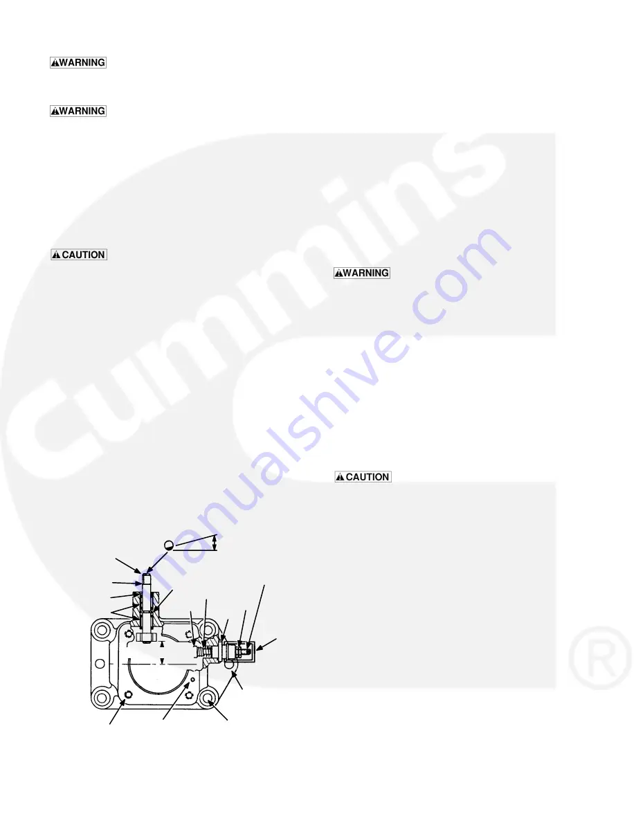
A spring and plunger assembly on the side of the pump
adapter (Figure 4-7) on the DJE generator set limits the
maximum power output of the engine for safe operation
and permits maximum fueling during starting.
Do not change the adjustment of this de-
vice unless absolutely required. The warranty may
be voided if the fuel stop is intentionally altered to in-
crease engine power.
15 DEGREES
SPRING
LOCK
NUT
FS1852C
FIGURE 4-7. INJECTION PUMP ADAPTER ASSEMBLY
TOP END
SHAFT POSITION
OF FLAT FOR
INSTALLING PUMP
TO ADAPTER
SHAFT
AND YOKE
ASSEMBLY
SEAL
BEARINGS
OVERLOAD FUEL PLUNGER
ADJUSTED AT FACTORY -
DO NOT CHANGE
GUIDE
PLUNGER
DUST
COVER
ADAPTER
DOWEL PIN
HOLES (2)
ADAPTER MOUNTING
BOLT HOLES (4)
DOWEL PIN HOLE
(BRYCE ONLY)
PUMP MOUNTING
HOLES (4)
EXTERNAL
RETAINING
RING
1 INCH (25.4 MM)


