background image

SPS1M

EVK

www.onsemi.com

2

Launching Sensor Software

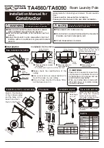
To launch the handheld Sensor software, double

click the “My Device” icon on the Desktop. Then double

click “Flash”,

then the “Sensor_xxxxx” folder, and finally the “Sensor” icon as shown in Figure 3.

Figure 3. Launching the Sensor Software

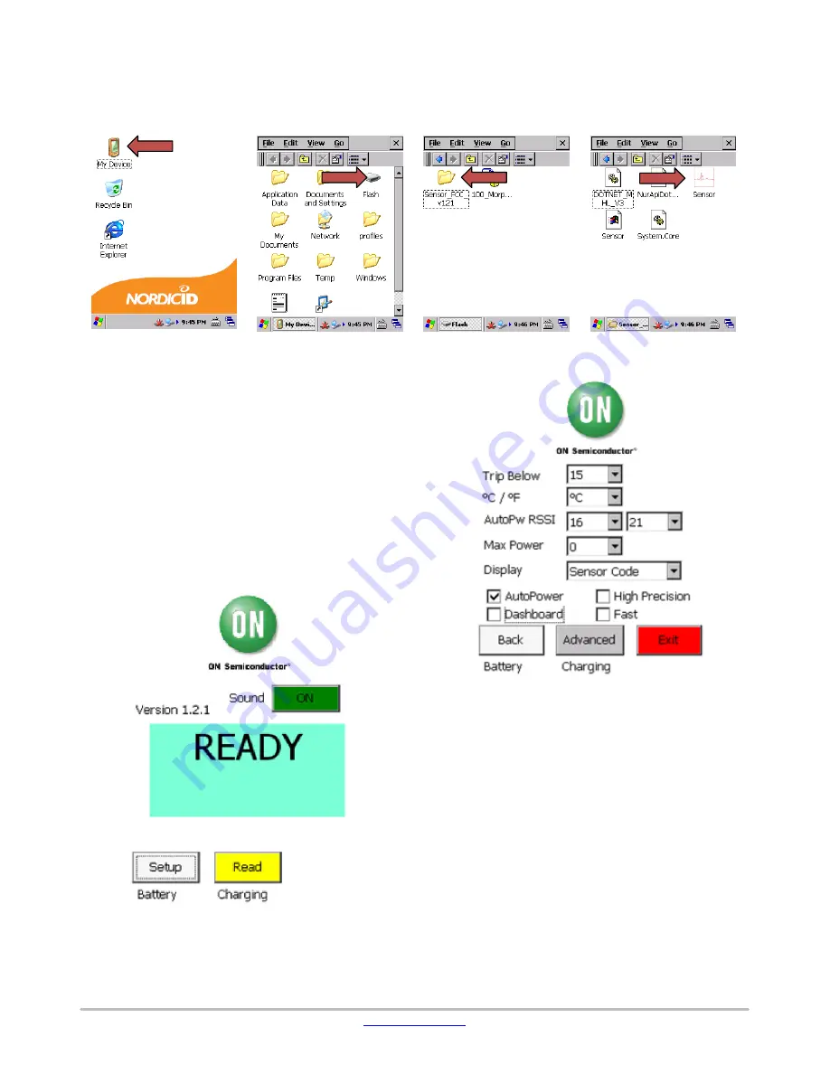
At startup, the handheld screen looks like the screenshot

in Figure 4. The following controls are available:

Read 

button: Starts the sensor read process. Pressing

the round yellow button on the keypad also starts a read

Setup 

button: Opens the Setup screen with additional

controls

Sound 

button: Toggles on and off the beep which

sounds when a read is complete

The battery indicator is at the bottom of the screen

.

 It gives

the battery charge percentage or reads “Charging” when the
unit is plugged in

.

Figure 4. Main Screen

The Setup screen is shown in Figure 5

.

Figure 5. Setup Screen

The following controls are available:

Buttons

Back

: Returns to the main screen

Advanced

: Opens the Advanced screen with

additional settings

Exit

: Quits the application

Pulldowns

Trip Below

: When the measured Sensor Code is

lower than this value, the main screen can optionally
display a message and a background color

5

C / 

5

F

: For temperature measurements, chooses

Celsius or Fahrenheit units

Summary of Contents for SPS1M-EVK

Page 1: ...the software on the reader it is not necessary for normal use The reader has a power plug for charging without the cradle To use the cradle plug in the USB cable and power cable to the back of the cr...

Page 2: ...Setup screen with additional controls Sound button Toggles on and off the beep which sounds when a read is complete The battery indicator is at the bottom of the screen It gives the battery charge per...

Page 3: ...f the Sensor Code result is above the trip value defined in the Setup screen the result will displayed with this background color No Trip Phrase If the Sensor Code result is above the trip value defin...

Page 4: ...SI pulldowns in the Setup screen The recommended minimum and maximum target On Chip RSSI values are 16 and 21 AutoPower attempts to quickly find a transmit power which results in an On Chip RSSI withi...

Page 5: ...pendicular to the face of the antenna The reader antenna should be aimed at the sensor tag and the tag oriented such that its long axis is perpendicular to the RF beam Figure 10 Figure 10 Proper Reade...

Page 6: ...r area Troubleshooting If the reader cannot read sensor tags or only reads tags from a short distance try the following steps Verify that the maximum reader power is set to 0 Move the tag to a differe...

Page 7: ...ems or any FDA Class 3 medical devices or medical devices with a similar or equivalent classification in a foreign jurisdiction or any devices intended for implantation in the human body Should you pu...

Reviews: