background image

Chapter 2: Safety

2.1 Dangers, Warnings, and Cautions

There are three levels of alert notation used in our manuals. In descending order of import-
ance, they are:

!

DANGER:

Identifies an imminently hazardous situation which, if not

avoided, is likely to result in serious injury, and might result in fatality or
severe property damage.

!

WARNING:

Identifies a potentially hazardous situation which, if not avoided,

will result in minor or moderate injury, and might result in serious injury, fatal-
ity, or significant property damage.

!

CAUTION:

Identifies a potentially hazardous situation which, if not avoided,

might result in minor injury, moderate injury, or property damage.
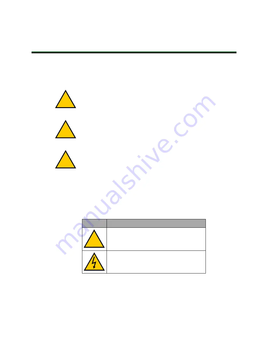
Alert Icons

The icon that starts each alert can be used to indicate the type of hazard. These will be used
with the appropriate signal word - Danger, Warning, or Caution - to indicate the severity of the
hazard. The text following the signal word will specify what the risk is, and how to avoid it.

Table 2-1. Alert Icon Meaning

Icon

Meaning

!

This is a generic alert icon. Any specifics on the
risk will be in the text following the signal word.

This identifies a hazardous electrical situation.

14362-000 Rev. D

SmartVision MX User's Guide

11

Summary of Contents for SmartVision MX

Page 1: ...I608 E 03 SmartVision MX Userʼs Guide ...

Page 2: ...mentation is periodically reviewed and revised Omron Adept Technologies Inc assumes no responsibility for any errors or omissions in the doc umentation Critical evaluation of the documentation by the user is welcomed Your comments assist us in preparation of future documentation Please submit your comments to techpubs adept com Copyright 2014 2017 2019 by Omron Adept Technologies Inc All rights re...

Page 3: ...ire Response 12 2 3 Safety Precautions 12 2 4 Additional Safety Information 13 Manufacturer s Declarations 13 Robot Safety Guide 13 2 5 Disposal 13 Chapter 3 Installation 15 3 1 Inspecting 15 3 2 Transport and Storage 15 3 3 Mounting the SmartVision MX 15 Vertical Mounting 16 Desk top Mounting 16 Stack Mounting 16 3 4 Connecting Power 18 External Power Supply 18 Recommended Power Supplies 19 Recom...

Page 4: ... 2 Turning Power ON and OFF 27 5 3 Checking the Licenses on the Dongle 27 Chapter 6 Technical Specifications 29 6 1 Processor Specifications 29 6 2 Environmental Specifications 29 6 3 Power Requirements 29 6 4 Dimensions 30 6 5 Connections 31 6 6 Camera Specifications 32 Chapter 7 Options 33 7 1 License Options 33 Software License Details 33 7 2 Mounting Options 33 Mounting Kits 33 4 SmartVision M...

Page 5: ...ting bracket part number in Chapter 3 Installation l Updated illustrations with call outs for translation com patibility and other minor improvements l Updated Chapter 2 Safety with new format and inform ation l Replaced discontinued S8JX G power supply with replacement S8FS G series l Added missing captions to tables l Added bracket number detail and adjusted figures in Chapter 3 Installation l A...

Page 6: ......

Page 7: ...ng a USB or GigE camera along with ACE s PC based vision soft ware the unit is a complete industrial vision solution When used with a SmartController the SmartVision MX provides expanded vision processing power for vision guided robotics or inspection Figure 1 1 The SmartVision MX Industrial PC Features The SmartVision MX provides the following features l Compatibility with the SmartController lin...

Page 8: ...recommend that you leave this write filter enabled for C in normal use Because the OS and ACE software are on C you should be very cautious about using C for any other purpose particularly for other applications l Matching connector for VDC input power l A USB license dongle which enables licenses for one or more of the following o ACE Sight software 2 camera support ACE 3 7 license does not restr...

Page 9: ...hard drive l Windows 7 Embedded l ACE l ACE Sight 3 ACE based vision software l Drivers for Basler ACE cameras USB and GigE The SmartVision MX is designed to run ACE software We do not support applications other than ACE Options For details on options see Options on page 33 l Extended licenses enabled on the USB license dongle l Stack mounting brackets 14362 000 Rev D SmartVision MX User s Guide 9...

Page 10: ...elp For details on getting assistance with your software or hardware you can access the corporate website http www ia omron com Related Manuals This manual covers the installation and use of a SmartVision MX The following manuals provide information on safety related products advanced configurations and system spe cifications Table 1 1 Related Manuals Manual Title Description Robot Safety Guide Co...

Page 11: ...ificant property damage CAUTION Identifies a potentially hazardous situation which if not avoided might result in minor injury moderate injury or property damage Alert Icons The icon that starts each alert can be used to indicate the type of hazard These will be used with the appropriate signal word Danger Warning or Caution to indicate the severity of the hazard The text following the signal word...

Page 12: ... on a yellow background and then follow the internal procedures of your company or organization for an emergency situation Fire Response If a fire occurs use CO2 to extinguish the fire 2 3 Safety Precautions WARNING ELECTROCUTION RISK During maintenance disconnect AC power from the robot and install a lock out tag out to prevent anyone from reconnecting power WARNING PERSONAL INJURY OR PROPERTY DA...

Page 13: ...tion We provide other sources for more safety information Manufacturer s Declarations This lists the standards with which our robots and controllers comply The Manufacturer s Declarations are in the Manufacturer s Declarations Guide Robot Safety Guide The Robot Safety Guide provides detailed information on safety for our robots It also gives resources for more information on relevant standards It ...

Page 14: ......

Page 15: ... Get Help section on page 15 Retain all containers and packaging materials These items may be needed in the future to settle a damage claim Remove the SmartVision MX Mount it near the robot 3 2 Transport and Storage The SmartVision MX must be shipped and stored in a temperature controlled environment within the range 25 to 60 C 13 to 140 F The recommended humidity range is 5 to 90 non condensing I...

Page 16: ...ssor to a ver tical surface The screw length is determined by the surface being mounted to Desk top Mounting Use 6 32 UNC screws or screws of similar specifications for mounting the processor to a flat surface The screw length is determined by the surface being mounted to Stack Mounting The SmartVision MX industrial PC can be stack mounted on top of a SmartController if there is one in the system ...

Page 17: ...ket l M3x10 stainless socket head cap screws l M3 high collar split lock washers l M3 stainless flat washers Tighten the M3 screws to 1 2 N m 10 6 in lbf There are two sets of two threaded holes on each side of the ventilation holes on the sides of the SmartController case See the following figure 2 Screw the SmartVision MX industrial PC to the top of the brackets using the mounting tabs on the bo...

Page 18: ...r age rating of the cable used Power Cabling 1 5 to 1 85 mm2 16 to 14 AWG full cover braided shield cable maximum length 10 meters Shield Termination Braided shield connected to the left wire slot of the VDC connector on the power side of the SmartVision MX On the other end of the cable the shield should be connected to the power sup ply chassis CAUTION Make sure you select a 24 VDC power supply t...

Page 19: ...ble is 10 meters Use the supplied connector to connect the user supplied 24 VDC power supply to the SmartVi sion MX 1 Locate the 24 VDC connector that is shipped with the SmartVision MX industrial PC See the following figure 2 Strip 7 mm of insulation from the end of the wire that connects to the positive output of the 24 VDC supply 3 Insert the stripped end of the wire into the opening on the rig...

Page 20: ...ed cable to SmartVision MX using left wire slot in 24 VDC connector 2 Use connector supplied at this end of cable 3 Optional fuse 4 Frame ground 5 Attach shield from user supplied cable to frame ground on power supply 6 User supplied power supply circuit protection 8 A Connecting to a SmartController The 24 VDC power cable is user supplied 1 Connect a 24 VDC cable from XDC1 or XDC2 on the controll...

Page 21: ...cting peripherals to the SmartVision MX industrial PC you may need to run a dedicated 24 VDC cable to the SmartVision MX industrial PC rather than tapping power from the controller or your power supply Make sure you are not exceeding the current capacity of the controller 24 VDC plug 3 5 Connecting Display Keyboard and Mouse To connect a display to the SmartVision MX industrial PC use either of th...

Page 22: ......

Page 23: ...le Camera Side 1 6 5 4 3 2 Figure 4 1 SmartVision MX Camera side Connectors Table 4 1 SmartVision MX Camera side Connector Descriptions Item Quantity Description 1 4 Gigabit Ethernet ports with Power Over Ethernet Ports 15 4 W max per port 2 1 DVI D Output Port 3 1 DVI I Output Port 4 4 USB 3 0 Ports 5 2 Gigabit Ethernet Ports 6 2 USB 2 0 Ports 14362 000 Rev D SmartVision MX User s Guide 23 ...

Page 24: ...MX Power side Connectors Table 4 2 SmartVision MX Power side Connector Descriptions Item Description 1 Power Button 2 Not Supported 3 Not Supported 4 Audio In Out Ports not used by software 5 RS232 RS485 Port 6 RS232 Port 7 Power Input Connector 9 to 36 VDC nominal 4 2 A 24 VDC 8 HDD LED 9 Power ON LED ...

Page 25: ... SmartVision MX We recommend that you use Category 5 or better wiring and connectors for your network NOTE If you are using a camera with a USB 2 0 connector or with an Ethernet connector that is not designed for PoE you will need to provide DC power to the camera through a separate cable 4 2 USB Ports For a USB 3 0 camera use one of the USB 3 0 ports To attach a USB peripheral plug the peripheral...

Page 26: ......

Page 27: ...pressing the button will turn it on The power button is on the power side of the processor where 24 VDC is connected When power is on the ON LED will be lit 5 3 Checking the Licenses on the Dongle You can see what has been enabled on a dongle with the following procedure 1 Turn on the SmartVision MX industrial PC and wait for it to finish booting 2 Double click the ACE icon on the desktop 3 Select...

Page 28: ......

Page 29: ... must be shipped and stored in a temperature controlled environment Refer to the following table Table 6 2 Environmental Specifications Ambient temperature 0 to 50 C 32 to 122 F Storage and shipment temperature 25 to 55 C 13 to 131 F Humidity range 10 to 90 non condensing 6 3 Power Requirements Table 6 3 Power Specifications Power Input 24 10 5 VDC Typical Power Consumption 4 2 A Maximum Power Con...

Page 30: ...th including tabs 260 mm 10 24 inches Width without tabs 225 mm 8 86 inches Depth excluding connectors 150 mm 5 9 inches Height 68 1 mm 2 68 inches 68 1 225 150 260 Figure 6 1 SmartVision MX Dimensions Units in mm 162 328 9 225 52 186 5 15 150 Figure 6 2 SmartVision MX Stack Mounted to SmartController EX Units in mm ...

Page 31: ...100 1000 Ethernet x 6 4 are PoE up to 15 4 W port l USB 3 0 x 4 l USB 2 0 x 2 One of these is used for the license dongle l DVI D output l DVI I output l RS232 RS485 port l RS232 port l Digital I O not supported 14362 000 Rev D SmartVision MX User s Guide 31 ...

Page 32: ...h CMOS Effective Pixels H x V 658 x 492 1296 x 966 1294 x 964 1602 x 1202 1600 x 1200 2048 x 2048 2046 2046 Color Mono chrome Color Mono chrome Color Mono chrome Color Mono chrome Color Frame Rate 120 fps 30 fps 30 fps 60 fps 60 fps 25 fps 25 fps Trigger input Software External Software Software External Interface Gigabit Ethernet 1 Gbit s Lens Mount ing C mount CS mount C mount C mount CS mount C...

Page 33: ... AdeptSight 3 0 ACE PackXpert License Required License Required AdeptSight 3 0 License Required License Required Additional Camera standard License Required Not Applicable Additional Camera color License Required Not Applicable ACE Controller License Required Not Applicable OPC Server License Required Not Applicable OPC Client License Required Not Applicable UI Builder Option License Required Not ...

Page 34: ...ting Kit Details Item Part Number Contents Mounting Bracket Kit 14391 000 l Bracket 2 x 14393 000 l M4 flat washer 4 x 54000 96700 l M4 lock washer 4 x 54100 96700 l M4x8 screw 4 x 09664 008 l M3 lock washer 8 x 00782 000 l M3x10 screw 8 x 51020 65010 l M3 flat washer 8 x 54000 96500 ...

Page 35: ......

Page 36: ...T TECHNOLOGIES INC 4550 Norris Canyon Road Suite 150 San Ramon CA 94583 U S A Tel 1 925 245 3400 Fax 1 925 960 0590 Regional Headquarters OMRON EUROPE B V Wegalaan 67 69 2132 JD Hoofddorp The Netherlands Tel 31 2356 81 300 Fax 31 2356 81 388 Contact industrial omron eu Kyoto JAPAN OMRON ASIA PACIFIC PTE LTD No 438A Alexandra Road 05 05 08 Lobby 2 Alexandra Technopark Singapore 119967 Tel 65 6835 3...

Reviews: