


94
Motion controllers
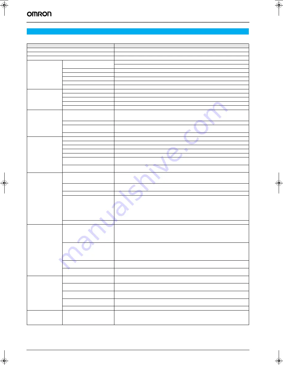
General specifications
Specifications
Item
Details
Type
R88A-MCW151-E, R88A-MCW151-DRT-E
Applicable servo drive
SGDH-
@@@
E models (software version 14 or later)
Installation method
Mounted on the SGDH servo drive side: CN10.
Basic
specifications
Power supply method
24 VDC (supplied from external power supply)
5 VDC (supplied from the servo drive control power supply)
Power consumption
4.0 W
External dimensions
20x142x128 mm (HxWxD)
Approx. mass
200 g
Current consumption
170 mA for 24 VDC
Output power supply
5 VDC, maximum 160 mA (to external encoder)
Environment
Operating temperature
0 … +55
°
C
Storage temperature
-20 … +75
°
C
Operating and storage humidity
90% RH max. (no condensation)
Vibration resistance
0.5 G (4.9 m/s
2
)
Shock resistance
2 G (19.6 m/s
2
)
Functional specifications Number of axes
- 1 controlled servo drive axis
- 1 master axis, encoder output axis or virtual axis
- 1 virtual axis
Servo loop cycle
Selectable to 0.5 ms or 1.0 ms.
Registration inputs
2x MCW151 unit for encoder input axis
1x Sigma-II servo drive axis
Measurement units
User definable
Programming
Programming language
BASIC
Number of tasks
Up to 3 tasks running simultaneously plus the command line task
Max. number of programs
14
Available memory for user programs
128 KB
Data storage capacity
251 (VR) + 8000 (table)
Saving program data,
motion controller
Random access memory (RAM) and flash memory backup.
Saving program data,
personal computer
Motion perfect software manages a backup on the hard disk of the personal computer.
Motion control
Speed control
Inferred closed loop with PID, output speed and speed feed forward gains
Speed reference (open loop)
Possible torque limit operation
Torque control
Torque reference (open loop)
Possible speed limit operation
Control switch
Speed / torque control switching during operation
Positioning operations
Linear interpolation
Circular interpolation
CAM profile movement
Electronic gearbox link
Linked CAM profile movement
Linked move for any two axes
Adding axes
Acceleration/deceleration curves
Trapezoidal or S-curve
Servo drive access
Motion control
Speed control
Torque control
Position feedback
Driver enable
Driver print registration
Monitoring
Driver alarm and warning status
General driver status
Driver digital input
Driver analogue input
Driver limit switches
General control
Driver alarm reset
Driver reset
Parameter access
Read and write Pn parameters
Read Un parameters
External I/O
Encoder input
Line receiver input; maximum response frequency: 1500 kHz pulses (before multiplication)
Pulse multiplication: x4
Encoder output
Line receive output; maximum frequency: 500 kHz pulses
Internal counts to output pulse ratio: 64:1
Digital inputs
Total of 8 digital inputs can be wired and used for instance for limit switches, emergency stop and
proximity inputs. Two inputs can be used for registration of the encoder input/output axis.
Digital outputs
Total of 6 digital outputs can be wired and used for position dependent switching or other general
purposes.
Registration inputs
Two registration inputs can be used (simultaneously) to capture the position in hardware.
Serial communications
RS-232C
Port 0:
Connection to PC (motion perfect software)
Port 1:
Host link master protocol
Host link slave protocol
General-purpose
Y203-EN2-02-Katalog.book Seite 94 Mittwoch, 24. Mai 2006 2:22 14


