30
2.
Installation and wiring
2.6 Pulse output wiring (continued)
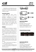
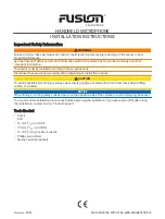
The following diagram shows wiring for pulse output.
This unit is equipped with 4 pulse outputs. The common terminal is used commonly.
The table below shows the output specifications.
Output capacity
DC40V, 50mA or less
Residual voltage when
ON
Less than 1.5V (when output current is 50mA)
Current leakage when
OFF
0.1mA or less
Pulse output units
1,10,100,1k,5k,10k,50k,100kWh
Pulse ON time
500ms fixed
Important
• The terminal is the push-in type. Also read "Cautions when connecting the Push-In Plus terminal (
when wiring.
• Do not directly connect an external power source to OUT or COM. Make sure the load is connected.
• To wire with the pulse output terminal, use AWG24-16 twisted or solid wire (with a cross-section of 0.25
to 1.5 mm
2
).
• Peel the wire-coating by 10 mm when using a ferrule terminal and by 8 mm when not using it.
• Use a ferrule terminal with a conductor portion 8mm long.
• To avoid the influence of noise, use separate wiring for the signals and for the power.
• Output for circuit A is allocated to OUT1, circuit B to OUT2, circuit C to OUT3, and circuit D to OUT4, and
these allocations are fixed.
−
+
Load
Load
Load
Load
−
+
Load
Load
Load
Load
PNP output connection diagram
NPN output connection diagram
DC40V(max)
50mA(max)
DC40V(max)
50mA(max)
OUT2
OUT3
OUT4
OUT1
COM
OUT2
OUT3
OUT4
OUT1
COM