background image

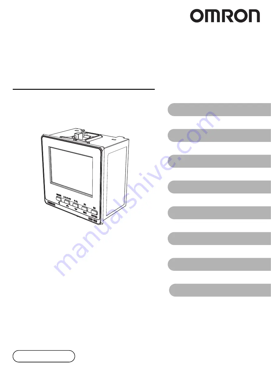
On-Panel Power Monitor

model

 KM-N3-FLK 

Users Manual

1. Overview of the unit

2. Installation and wiring

3. Basic use

4. Settings needed to measure 

electricity

5. Other Functions

6. Detailed settings for communications

7. Troubleshooting

8. Appendices

Catalog no.  N214-E1-02

Thank you for purchasing the On-panel Power Monitor, model KM-N3-
FLK (referred to as model KM-N3 in this manual).
This Users Manual describes the functions, performance, and 
application methods needed for optimum use of the unit. 

Please observe the following when using this unit. 
• This product is designed for use by qualified personnel with a

knowledge of electrical systems.

• Before using the product, thoroughly read and understand this Users

Manual to ensure correct use. 

• Keep this Users Manual in a safe location so that it is available for

reference whenever required. 

Summary of Contents for KM-N3-FLK

Page 1: ...or model KM N3 FLK referred to as model KM N3 in this manual This Users Manual describes the functions performance and application methods needed for optimum use of the unit Please observe the followi...

Page 2: ...uit metering 17 1 6 Multi address system 19 1 7 Mode configuration 20 2 Installation and wiring 2 1 Attaching the body of the unit 21 2 2 Wiringthe CTs 23 2 3 Wiring the power supply 25 2 4 Wiring the...

Page 3: ...ion 61 5 4 Automatic LCD OFF 62 5 5 Alarm display with negative effective power value 63 5 6 Tariff feature 64 5 7 Change password 65 5 8 Checking software version 66 5 9 Initialize 67 5 10 Restart 67...

Page 4: ...iscontinue the production of Omron Products or change their specifications for the purpose of improving such products or for other reasons entirely at its own discretion 3 Precautions You are deemed t...

Page 5: ...lfunction falls under any of the following a Usage in a manner other than the original intended use for the Omron Products b Usage other than as described in the Usage Conditions c Usage that is not i...

Page 6: ...on Indicates a potentially hazardous situation which if not avoided will result in minor or moderate injury or there may be property damage Mandatory actions Indicates a general action that must be pe...

Page 7: ...nally occur Use the power voltage and load within the specified and rate ranges Electric shock may occasionally occur Do not touch any of the terminals while the power is being supplied Electric shock...

Page 8: ...ion of 0 25 to 1 5mm2 to wire communication terminals The heat resistant temperature of the wire is 85 degree or more Before using or maintaining the product thoroughly read and understand this manual...

Page 9: ...hen cleaning the unit make sure the power is off and wipe the surface of the unit with a soft dry cloth Do not use chemicals including solvents such as thinners benzine or alcohol You cannot use the C...

Page 10: ...Confirm the voltage using the power supply voltage of the product that you purchased Short time overvoltage 1200 V power supply voltage Long time overvoltage 250 V power supply voltage For safety sta...

Page 11: ...talog number on the front cover and back cover of the manual Revision number Date of revision Reason for revision pages revised 01 A August 2016 First edition 02 July 2017 UL certified Description of...

Page 12: ...each able to be allocated different communications addresses You can manage individual circuits as electricity monitors from a host system so it is easy to build a communications system and add places...

Page 13: ...M20 CTF model series KM NCT etc with this unit Breaker On Panel Power Monitor Model KM N3 FLK For example PLC Pulse output 1 Host device RS 485 Modbus CompoWay F Generic CT Pulse output 2 Pulse output...

Page 14: ...ode The display of each resettable integrated electric energy is switched Communication address Menu display When ADDRESS is lit in the measurement mode The communication address is displayed When MEN...

Page 15: ...terminal RS 485 2 RS 485 terminal for transition wiring RS 485 2 RS 485 terminal for transition wiring RS 485E RS 485 terminating resistor terminal Pulse output terminal OUT1 Circuit A pulse output te...

Page 16: ...tely if it becomes lost or damaged The Waterproof Packing for the front panel Setup Tool port must be periodically replaced because they may deteriorate shrink or harden depending on the operating env...

Page 17: ...ses branching off a 1 phase 3 wire switchboard You can measure 1 phase 2 wire by selecting the corresponding voltage Set 1 phase 3 wire composite to measure both the main 1 phase 3 wire switchboard an...

Page 18: ...its B to D to increase the number of measurement points Settings for circuits B to D when measuring 2 circuits or more 52 you can meter electricity using the required number of circuits This are disab...

Page 19: ...e circuits at once Refer to 6 Detailed settings for communications 69 for details about commands responses and address maps Caution Each circuit on this product needs to be allocated different communi...

Page 20: ...to D items are displayed by switching the enable disable settings for each of the circuits to ON enabled The circuits indicated inside the dotted lines in the above diagram are OFF disabled in the def...

Page 21: ...a person working on the unit will not be able to touch live wires 1 Create an opening on the panel according to the panel machining dimensions Use a panel 1 to 8 mm thick 2 In order to make the unit...

Page 22: ...Terminal Cover Slightly bend the E53 COV24 Terminal Cover to attach it to the terminal block as shown in the following diagram The Terminal Cover cannot be attached in the opposite direction Importan...

Page 23: ...follows The following table shows the phase and wire types and the CT allocations for each measuring circuits Connect the CT cables for CT1 CT2 CT3 CT4 to the terminals on the main unit that are label...

Page 24: ...nger of electric shock Furthermore this may cause this unit and the CT to malfunction To wire the CT input terminals use AWG18 14 wire with a cross section of 0 75 to 2 0 mm2 and crimping terminals of...

Page 25: ...pply terminal use AWG20 16 twisted or solid wire with a cross section of 0 5 to 1 5 mm2 Peel the wire coating by 10 mm when using a ferrule terminal and by 8 mm when not using it Use a ferrule termina...

Page 26: ...W O or L1 L2 L3 N in some cases R N T may be labeled U O W or L1 N L2 in some cases To wire the voltage input terminal loosen the 3mm screw on the terminal panel push the wire completely into the term...

Page 27: ...ase sequence is correct You will be unable to measure the power and energy correctly if you fail to do so To wire the voltage input terminals use AWG18 14 wire with a cross section of 0 75 to 2 0 mm2...

Page 28: ...suring 1 phase 2 wire Attach to the R phase and T phase if measuring 1 phase 3 wire or 3 phase 3 wire Attach to the R phase S phase and T phase if measuring 3 phase 4 wire Refer to 2 8 Wiring diagrams...

Page 29: ...t terminals while pressing on the release hole Refer to Cautions when connecting the Push In Plus terminal 31 for details about wiring and connections Terminal number Terminal name Description 12 OUT1...

Page 30: ...n wiring Do not directly connect an external power source to OUT or COM Make sure the load is connected To wire with the pulse output terminal use AWG24 16 twisted or solid wire with a cross section o...

Page 31: ...the wires to the terminal block 1 1 Hold a flat blade screwdriver at an angle and insert it into the release hole The angle should be between 10 and 15 If the flat blade screwdriver is inserted corre...

Page 32: ...release hole remove the wire from the terminal insertion hole 3 Remove the flat blade screwdriver from the release hole 3 Recommended Tools ecommended Flat blade Screwdriver Use a flat blade screwdriv...

Page 33: ...al while pressing on the release hole Refer to Cautions when connecting the Push In Plus terminal 31 for details about wiring and connections Terminal number Terminal name Description 4 RS 485 termina...

Page 34: ...for your purpose Important The terminal panel is the push in type Also read Cautions when connecting the Push In Plus terminal 31 when wiring The addresses for circuits B to D are automatically set w...

Page 35: ...phase 4 wire measures one circuit as shown in the following diagram For 1 phase 2 wire As shown below 1 phase 2 wire can measure a maximum of 4 circuits The CT must be attached to the L phase Power si...

Page 36: ...must be attached to the R phase and the T phase For 3 phase 3 wire As shown below 3 phase 3 wire can measure a maximum of 2 circuits Use CT1 CT2 when measuring only 1 circuit The CT must be attached...

Page 37: ...the R phase or the T phase For 1 phase 3 wire composite The 1 phase 3 wire circuit and the 1 phase 2 wire branching off from it are measured at the same time With this connection a setting is required...

Page 38: ...n display and model KM N3 is displayed on the first display The system moves to the measurement mode automatically displaying the effective power of circuit A each phase kW and the integrated effectiv...

Page 39: ...e measuring mode by sending particular commands Refer to 6 Detailed settings for communications 69 for details about the commands to move to each mode Switching from measuring mode to communication se...

Page 40: ...ing mode How to enter the password When moving from the measuring mode to the setting mode you need to enter the password that has been set The default password is 0001 You can set a password of 4 num...

Page 41: ...layed if you have enabled the circuit settings 52 MODE MODE MODE MODE MODE MODE MODE MODE MODE MODE MODE MODE MODE MODE MODE MODE MODE 3 phase 4 wire 3P4W 1 phase 2 wire 1P2W 1 phase 3 wire 1P3W 3 pha...

Page 42: ...ntegrated value display is switched Switching the measured values display The measurement items are switched by pressing the I V F PF key P Q key E1 key or E2 key Depending on the phase and wire type...

Page 43: ...oltage A 1 0 000 to 9999 V kV 3 Voltage B 2 0 000 to 9999 V kV 4 Frequency 45 0 to 65 0 Hz 5 Power factor 1 00 to 1 00 PF 1 P Q Active power each phase 9999 to 9999 kW MW 2 Active power total 9999 to...

Page 44: ...l setting items for the circuits Common CMMN Setting items common to all of the circuits communication pulse output etc Others ETC Settings for initializing resetting cumulative values etc MODE MODE M...

Page 45: ...setting items for circuits B to D are displayed when the circuit settings are enabled ON Press the keys to switch the setting items Refer to Setting item list 46 for details about all of the setting i...

Page 46: ...5 Voltage assignment V_R V_T V_R T V_R Set the voltage phase for 1 phase 2 wire circuits when 1P2W2 is selected B6 Pulse output ON OFF ON OFF OFF B7 Active energy reset Clear the active energy for the...

Page 47: ...0 to 99 999 10 000 Set the conversion factor by which active energy is multiplied for each circuit 08 Pulse output units 1 10 100 1K 5K 10K 50K 100K Wh 100 09 Automatic LCD off OFF 1 0 5 0 10 0 minute...

Page 48: ...nd wire type CT secondary side current CT primary side current Communication address Pulse output ON OFF Circuit B to D setting items 52 Circuit ON OFF CT secondary side current CT primary side curren...

Page 49: ...default value Press the MODE key to move one place to the left If you press the MODE key on the end at the left the cursor moves to the right end 4 The password is verified when you press the ENTER ke...

Page 50: ...on the table below are assigned automatically 2 The communication addresses of circuits B D cannot be set up individually 4 Set the CT secondary side current Ex set to 1A 1 From the circuit A setting...

Page 51: ...d 6 Set pulse output ON or OFF MENU A6 Ex set to ON 1 From the circuit A setting item press the keys to move to Pulse output ON OFF MENU A6 2 Press the ENTER key to enter the setting mode 3 Press the...

Page 52: ...C Circuit C ON OFF MENU C0 is displayed 2 Press the ENTER key to enter the setting mode 3 Press the keys to select ON 4 Press the ENTER key to confirm your selection 2 Set the CT secondary current fo...

Page 53: ...press the keys to move to Pulse output ON OFF MENU C6 2 Press the ENTER key to enter the setting mode 3 Press the keys to select ON 4 Press the ENTER key to confirm your selection The menu numbers to...

Page 54: ...to the setting mode 1 Press the MODE key to move to the common settings CMMN category display screen After this the screen moves automatically to the common settings items and Protocol MENU 00 is dis...

Page 55: ...dbus the data bit length is fixed at 8bits Set the stop bit length Ex set to 2 bits Can only be set when the protocol is CompoWay F 1 Press the MODE key to move to the common settings CMMN category di...

Page 56: ...smission wait time Ex set to 15 msec You can set the time to wait between when a response is created and when it is sent The setting can be changed in units of 1ms The default value is 20ms 1 Press th...

Page 57: ...or occurs The pulse output continues for more than 500ms due to the unit being exceeded again Output unit is exceeded within the OFF sustained width Action when error occurs Pulse is output within the...

Page 58: ...e is displayed press and hold the MODE key and enter your password to switch to the setting mode 1 Press the MODE key to move to the settings category display screen for circuit C 2 From the circuit C...

Page 59: ...s CMMN category display screen 2 From the common setting items press the keys to move to VT ratio MENU 06 3 Press the ENTER key to enter the setting mode The second decimal place of the setting value...

Page 60: ...setting mode 1 Press the MODE key to move to the common settings CMMN category display screen 2 From the common setting items press the keys to move to Conversion rate MENU 07 3 Press the ENTER key to...

Page 61: ...off time Ex set to 10 minutes If a measured value is displayed press and hold the MODE key and enter your password to switch to the setting mode 1 Press the MODE key to move to the common settings CM...

Page 62: ...wiring and input are corrected Set the alarm display with negative effective power value Ex set to OFF If a measured value is displayed press and hold the MODE key and enter your password to switch t...

Page 63: ...urrent tariff default value is T1 The value for the current tariff can only be changed from the communication settings 69 Set the tariff function Ex set to ON If a measured value is displayed press an...

Page 64: ...change to 3060 Press the MODE key to move one place to the left If you press the MODE key on the end at the left the cursor moves to the right end 5 ONCE AGAIN is displayed when you press the ENTER k...

Page 65: ...and hold the MODE key and enter your password to switch to the setting mode 1 Press the MODE key to move to the other settings ETC category display screen Next the display automatically transitions to...

Page 66: ...active energy for each circuit example resetting circuit A If a measured value is displayed press and hold the MODE key and enter your password to switch to the setting mode 1 From the circuit A setti...

Page 67: ...1 is displayed again Resetting the active energy and setting values for all circuits If a measured value is displayed press and hold the MODE key and enter your password to switch to the setting mode...

Page 68: ...gs ETC category display screen 2 From the other setting items press the keys to move to Restart MENU 93 3 When you press and hold the ENTER key the dashes reduce from the left side of the main screen...

Page 69: ...The host device a computer for example sends the command frame and model KM N3 sends the response frame that corresponds to the command content So 1 response frame is sent in response to one command f...

Page 70: ...address of this product Figures in hexadecimal format between H 01 to H 63 01 to 99 can be set Specify H 00 to communicate to all at the same time There will be no response if this is specified howeve...

Page 71: ...egister and the next byte of data return that result to the CRC register and repeat step 3 6 The calculated result the value of the CRC register is appended to the message starting from the lower byte...

Page 72: ...ording to commands 08 H 08 Echo back test Echo back test is performed Error code Name Description Error detection Priority H 01 Function code error Using an unsupported function code 1 H 02 Variable a...

Page 73: ...the measuring mode or the setting mode Also measuring continues even while in the setting mode Command frame Start reading address Specify the address for the measurement value or setting data you wan...

Page 74: ...the calculation 71 Command Response example The following is an example of reading voltage 1 Communication address When H 01 Command Response Commu nication address Function code Byte Counter Data 1...

Page 75: ...Start writing address Specify the address for setting data you want to write Refer to 6 4 Address map 93 for the address Number of elements Specify the number of pieces of data that you want to write...

Page 76: ...lculation 71 Command Response example The following shows an example of writing when changing the phase and wire type to 1 phase 2 wire Communication address When H 01 Address H 2000 Written data H 00...

Page 77: ...umbers Commu nication address Function code Start writing address Written data CRC 16 H 06 H FF H FF Fixed Fixed 1 1 2 2 2 Commu nication address Function code Start writing address Written data CRC 1...

Page 78: ...address Set 0000 as the address for the echo back test Test data This is any data in 2 byte HEX format Commu nication address Function code Start writing address Written data CRC 16 01 06 FFFF 0300 89...

Page 79: ...for the communication frame H 02 Make sure you set this code as the first byte Communication address Specify the communications address of this product You can set a number between 00 and 99 or XX up...

Page 80: ...ddress Exit code Command text BCC STX 0 0 ETX Fixed Fixed 1 2 2 2 1 1 Exit code Name Description Error detection Priority 00 Normal end This indicates that the command ended normally and that there wa...

Page 81: ...the sub request code SRC and the data required by these and these are transferred Service request PDU Continuing on from the above MRC and SRC main response codes MRES and sub response codes SRES are...

Page 82: ...e parameter values for various settings MRC SRC Service name Processing 01 01 Read variable area Variable area is read 02 01 Read parameter area Parameter area is read 02 02 Write parameter area The p...

Page 83: ...ough 3 1003 Mismatched element and data numbers There is a mismatch between the number of elements and the number of pieces of data 6 1100 Parameter error The parameter value is unsupported 8 1101 Are...

Page 84: ...id addresses of the variable area then if the number of data up to the end of the end address is within the range specified by the number of elements reading is done and the end is normal In this case...

Page 85: ...nd Response This product converts measured values to hexadecimal without decimal points for response H 0000040D would be 1037 in decimal H 02 00 00 0 01 01 C0 0000 00 0002 H 03 H 42 STX Commu nication...

Page 86: ...e number of elements reading is done and the end is normal In this case the number of data read will be fewer than the number of elements specified in the command Further if the start reading address...

Page 87: ...and wire type is 1 phase 2 wire H 00000000 is read The communications address will be H 0000000A 10 decimal H 02 10 00 0 02 01 C000 1000 8002 H 03 H 49 STX Commu nication address Sub address SID MRC...

Page 88: ...eds the valid addresses of the variable area then if the number of data up to the end of the end address is within the range specified by the number of elements writing is done and the end is normal I...

Page 89: ...if the model doesn t take up 10 bytes For example This will be as follows for model KM N3 FLK Buffer size The buffer size 230 is read as 00E6 fixed value Response code Refer to List of response codes...

Page 90: ...appear as follows Displayed as 01 in the PDU MRC SRC 0 6 0 1 2 2 MRC SRC Response code Operational state Related information 0 6 0 1 2 2 4 2 2 Operational state Description 00 The unit is measuring wi...

Page 91: ...est is performed Service request PDU Service response PDU normal Test data Set any test data within the range 0 to 200 Response code Refer to List of response codes for details about each response cod...

Page 92: ...e code Refer to List of response codes for details about each response code 83 MRC SRC Instruction code Related information 3 0 0 5 2 2 2 2 MRC SRC Response code 3 0 0 5 2 2 4 Instruction code Related...

Page 93: ...active power 1 Watt x 10 R 0011 0022 Reactive power 2 Watt x 10 R 0012 0024 Reactive power 3 Watt x 10 R 0100 0200 Measured value integration Unable to reset Integrate effective energy Wh R 0101 0202...

Page 94: ...Integrated T3 effective energy Wh R 0128 0250 Integrated T4 effective energy Wh R 0130 0260 Measured value integration 2 Able to reset Integrate effective energy kWh R 0131 0262 Integrate regenerative...

Page 95: ...009 2012 Voltage selected 0 V_R 1 V_T 2 V_R T R W 100A 2014 CT secondary side current H 00000000 1A H 00000001 5A R W 100B 2016 CT primary side current x1 value of amperage 1 to 9999 R W 1100 2200 Com...

Page 96: ...Factor x 100 0 to 99999 R W 110A 2214 LCD OFF waiting time 0 OFF 1 1 minute 2 5 minutes 3 10 minutes R W 110C 2218 Alarm ON OFF 0 OFF 1 ON R W 110D 221A Tariff ON OFF 0 OFF 1 ON R W 110E 221C Current...

Page 97: ...alue error Calibration value is corrupted Alarm Input frequency warning Measured frequency is outside rated ranges Input the power and voltage with the frequency within the rated ranges VR phase warni...

Page 98: ...to the main unit Also check if the CT has become separated from the electric wire 23 Is the connection positioning of the measuring circuits and the CT terminals correct Circuit A uses CTs 1 2 or 3 ci...

Page 99: ...corresponds to circuits C and D 52 Has the input exceeded the input range of the CT Check the secondary current and primary current of the CTs you are using and use CTs that have appropriate rated cu...

Page 100: ...maximum number of units you can connect when the protocol is Modbus is 99 units and when the protocol is CompoWay F the maximum is 31 The parent device is not included in either of these numbers 33 H...

Page 101: ...try and case 20M max at DC500V mega 2 Between the batch input of power supply voltage and current and the set of communication terminals and pulse output terminals 20M max at 500 VDC mega Vibration re...

Page 102: ...3 wire 173 to 480 VAC L L Variation range of input voltage 85 to 110 of rated input voltage Connectable CTs Generic CT Secondary rated current 1A or 5A Rated current for CT secondary side 1A Maximum...

Page 103: ...101011 43 2B i 0001100 12 C FF 0101100 44 2C 0001101 13 D CR 0101101 45 2D 0001110 14 E SO 0101110 46 2E 0001111 15 F SI 0101111 47 2F 0010000 16 10 DEL 0110000 48 30 0 0010001 17 11 DC1 0110001 49 31...

Page 104: ...001011 75 4B K 1101011 107 6B k 1001100 76 4C L 1101100 108 6C l 1001101 77 4D M 1101101 109 6D m 1001110 78 4E N 1101110 110 6E n 1001111 79 4F O 1101111 111 6F o 1010000 80 50 P 1110000 112 70 p 101...

Page 105: ...following are some examples of 14 segment displays and 7 segment displays as shown on the LCD of this product N E D C B A J I H G F M L K O Y R Q P W V U T S Z X 5 4 3 2 1 0 9 8 7 6 1 2 3 4 5 6 7 8 9...

Page 106: ...IL 60169 U S A Tel 1 847 843 7900 Fax 1 847 843 7787 Regional Headquarters OMRON EUROPE B V Wegalaan 67 69 2132 JD Hoofddorp The Netherlands Tel 31 2356 81 300 Fax 31 2356 81 388 Contact www ia omron...

Reviews: