※
Communication between front door camera and audio phone is unavailable.
�
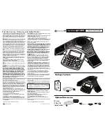
Wiring for multi houses (apartment) using KLP-C100 series Lobby phone.
- Video phone to Audio phone wiring in a house.
※
Cautions
1. Terminal No. 5(data line) in sub audio phone is not connected from Pin No. 6(data line) of main
monitor.
2. Pin No. 1, 2, 3, 4, 7 & 8 in Main Line Port (Monitor) are used in a form of parallel connection
between main monitor and sub audio phone (1, 2, 3, 4, 6, 7).
3. In extention with KIP-603 (Audio phone), it is not available to make conversation with the front
door camera.
4. The DIP switch in sub unit should be set as “0”.
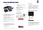
Instructions for Operation
�
Functional Descriptions
▷
▷
Communication with front door when a visitor comes :
When a visitor presses the call button of front door camera,
1. Call signal rings at home monitor and its screen is automatically turned on to display a visitor.
2. If pressing communication button or front door button on the front side of videophone,
user can communicate with the visitor at front door.
(The monitor screen will be automatically faded out after 30 seconds)
3. If pressing communication button or front door button again after communication with
the visitor, user can end the communication (and screen is also faded out). If user wants to keep
communicating, press front door button again to connect to front door camera and then press
communication button .
By doing so, monitor screen is turned on and user can keep communicating with the visitor. (While
communicating with the visitor, if user presses the door open button , house front door
will be opened.)
▷
▷
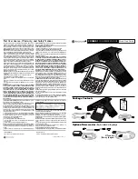
Monitoring of Front Door Situations
1. Monitoring for Camera 1
- If pressing the front door button once on the monitor, the image from camera 1 port is displayed
on the monitor screen.
2. Monitoring for Camera 2
- If pressing the front door button once on the monitor, the image from camera 1 port is displayed
on the monitor screen. And if pressing the front door button once again, the image from
camera 2 port is displayed on the monitor screen. Then, if pressing the front door button once
again, the monitor screen is turned off.
3. In case only one camera is installed
- If pressing the front door button , the image is displayed on the monitor screen.
If pressing once again, there will be no image displayed on the monitor screen.
- In case camera 1 is connected to the camera port 2 at the back of the monitor.
If pressing the front door button once, there is no image displayed and then if pressing once
again, the image from camera port 2 is displayed. In this case, if you change the camera 2 port to
1 port, it will work in normal.
4. In case two cameras are installed.
- If pressing the front door button once, the image from camera 1 is displayed and if pressing
once again, the image from camera 2 is displayed. If pressing one more, the monitor
screen is turned off.
- Cautions : Be careful for wrong connection between cameras and camera ports.
14
15
Summary of Contents for KIV-212
Page 2: ...2 3 ...
Page 3: ...4 5 ...