background image

6

LIF TKIT- O M

6

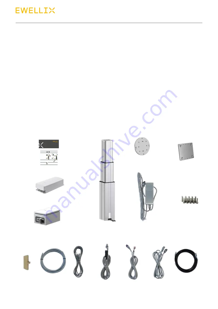
3.0  LIFTKIT components

Lifting column TLT

EHA3A operating 
handswitch

Screws 

for 

mounting plates

Control unit SCU16/56/96

Omron attachment plate

Bottom mounting plate

SBOX

Controller 
I/O cable

RS232 interface 
cable

SBOX
I/O cable

SBOX Key

Ethernet 
cable

SBOX to controller 
power cable

SBOX power 
cable

Quick start guide

LIF TKIT

QUICK START GUIDE

LIFTKIT

For more details on each step, read the corresponding installation, operation and maintenance manual. 

Please check on ewellix.com/products/telescopic-pillars/liftkit.

1.  Mount interface plates to 

pillar (top and bottom)

2.  Connect all cables

3.  Initialize LIFTKIT (First use only!)

LIFTKIT-UR

Others

3.1. Press both handswitch buttons at the same 

time, until controller beeps (5sec)

3.2. Move pillar downwards until end stop (beep)
3.3. Move pillar upwards until end stop (beep) 

4.  Screw robot to pillar, install 

URCaps software

ewellix.com 

© Ewellix
All contents of this publication are the property of Ewellix, and may not be reproduced or given to third parties (even extracts) without permission. Although great care has been taken in the 
production of this catalog, Ewellix does not take any responsibility for damage or other loss resulting from omissions or typographical errors. The photo may differ slightly in appearance from the 
actual product. Due to continuous improvements being made in our products, the product’s appearance and specifications are subject to change without notice.

PUB NUM TC-08048-EN-March 2021

Setting up LIFTKIT 

Motion control

Controller

Robot 

attachment 

plate

Electrical 

230/120 V AC

24 V DC

Electrical 

230/120 V AC

Controller 

Robot controller

(not included 

in LIFTKIT-0S)

Robot 

attachment 

plate 

SBOX

3.1  Scope of delivery

•  1 Lifting column TLT
•  1 Control unit SCU16/56/96
•  1 SBOX power cable EU/US/CH/CN
•  1 RS232 interface cable M/0133976
•  1 Controller I/O cable M/0133975
•  1 EHA3A operating handswitch
•  1 OMRON attachment plate 
•  1 bottom mounting plate

•  8 M10x40 screws for mounting plates
•  4 screws M6x20 for OMRON robot 
•  2 pins ᴓ 8x20 to align OMRON robot 
•  Quick start guide
•  1 SBOX
•  1 SBOX key
•  1 SBOX I/O cable
•  1 SBOX to controller power cable
•  1 Ethernet cable
•  SBOX mounting attachments

Summary of Contents for Ewellix LIFTKIT-OM

Page 1: ...CATEGORY MAX 2 LINES INSTALLATION OPERATION AND MAINTENANCE MANUAL LIFTKIT OM...

Page 2: ...2 1 Intended use 5 2 2 Safety elements 5 2 3 Application notes 5 2 4 Potential risks 5 2 5 E Stop setup and behavior 5 3 0 LIFTKIT components 6 3 1 Scope of delivery 6 4 0 Mechanical installation 7 4...

Page 3: ...personnel working with the de vice must read and understand this manual before starting any work Strict compliance with all specified safety notes and instructions is a basic requirement for safety a...

Page 4: ...x com TC 08023 EN May 2020 THG TLG TLT operating manual TC 08005 EN March 2020 SCU operating manual 1 5 Target audience This manual is intended for qualified technical personnel who install and use LI...

Page 5: ...chain of the complete system prior to operating LIFTKIT The emergency stop function has to be connected in such a way that a disruption of the power supply or the activa tion of the power supply after...

Page 6: ...produced or given to third parties even extracts without permission Although great care has been taken in the production of this catalog Ewellix does not take any responsibility for damage or other lo...

Page 7: ...ing at least four attachment holes on the plate 3 a Alternatively if mounting to a SLIDEKIT attach the bottom plate with 8x M6 screws to the LIFTKIT s attachment plate 5 Loosen and remove 4 transport...

Page 8: ...or 7 Ethernet Connector 8 K1 A1 9 K2 A1 10 K1 A2 11 K2 A2 12 K1 31 13 K1 32 14 K2 31 15 K2 32 A1 14 24 32 A2 13 23 23 24 13 14 A1 A2 31 32 31 1 2 3 4 5 6 7 8 9 10 11 12 13 14 15 5 2 Safety connection...

Page 9: ...9 5 0 Hardware connection SBOX 5 3 Schematic SBOX 5 4 LIFTKIT connection setup...

Page 10: ...ultaneously for about 5 seconds until the SCU rattles and beeps Now the pil lar will run at 50 speed and force 4 Move the pillar downwards until it hits the end position The SCU controller beeps 5 Mov...

Page 11: ...ila ble for LIFTKIT integration Command 7 2 Installation Download the zipped component file from the Ewellix web site https www ewellix com en gb products telescop ic pillars liftkit liftkit om 1 1 Ta...

Page 12: ...r_ Ewellix_LIFTKIT_v01_Command zip 3 Open the Import Export menu in TMflow then plug the USB drive into the robot controller or select the network drive as shown here 4 Select Import then select the c...

Page 13: ...t menu in the robot settings page then enable the Ewellix component Click Save when done 7 Now the component is ready for drag and drop use with TMflow projects 7 0 Software instruction for Ewellix LI...

Page 14: ...pecify Pillar IP Address does not reconfigure the pil lar s IP 2 Get Pillar Info such as current status current virtual lim its and current position 3 Set Pillar Info such as pillar type and virtual l...

Page 15: ...ded if the LIFTKIT IP address has been reconfigured by the user Get_Info Get_Info Settings var_GetInfo Function Determines whether the component will request information from the pillar using the Get...

Page 16: ...command is issued Use the get_type sAvailable command in the Get Info function of the compo nent for a list of acceptable pillar types Type String variable Default LIFTKIT 601 Set_Info Set_Info Settin...

Page 17: ...osition com mand Type Float variable Default 0 var_MoveTimeout_ms Function Sets the amount of time in ms for the pillar to reach its commanded position before timing out Type Integer variable Default...

Page 18: ...rror See Appendix A for a list of LIFKIT component error codes Type Integer variable ranges from 4000 4005 or 0 if there is no error Default 0 var_PreviousPosition Function If the Move_Absolute functi...

Page 19: ...nt Refer to the Ewellix LIFTKIT manual for more details on the available LIFTKIT commands allowed states and responses After each troubleshooting step repeat Step 3 c If the response from the pillar i...

Page 20: ...nough for the pillar to finish processing and sending the results to the TM 4002 Invalid State Pillar is in an invalid state for the specified command See Ewellix LIFTKIT manual for details 4003 Error...

Page 21: ...ool like a pliers 5 Download and install one of these tools Raspberry imager from https www raspberrypi org downloads balenaEtcher from https www balena io etcher 6 Copy Image on SD card 6 3 Place SD...

Page 22: ...sure that the 24 stays behind the static IP address 4 Put the file on an USB Stick 5 Remove all cables from the SBOX L 01 6 Open the Box 7 Insert USB Stick into the controller 8 Close the Box 9 Plug...

Page 23: ...23 3 0 Software operation 23...

Page 24: ...o PLe Cat 4 Communication Control interface TMflow Positioning repeatability mm 1 Accessible positions any Feedback Position Status Soft start and stop Implemented for smooth operation Software contro...

Page 25: ...40 83 5 27 6 40 40 8 M5 11 mm deep 340 141 5 2 13 5 50 5 75 75 360 365 87 Controller SBOX Robot attachment plate TLT Pillar Bottom fixation plate 180 70 140 200 180 146 4 11 mm 8 6 3 mm 15 Stroke 4 30...

Page 26: ...catalog Ewellix does not take any responsibility for damage or other loss resulting from omissions or typographical errors The photo may differ slightly in appearance from the actual product Due to c...

Reviews: