


・
Head ×1
・
Wrench ×1
・
Hose elbow ×1 (E9NC-TH
□
L
□
)
・
Clamp spanner, Pin, Tightening nut, Wave washer ×1 each (E9NC-TH
□□
F)
・
Manual (this paper) ×1 each
(
Japanese, English, Chinese
)
Checking the package contents
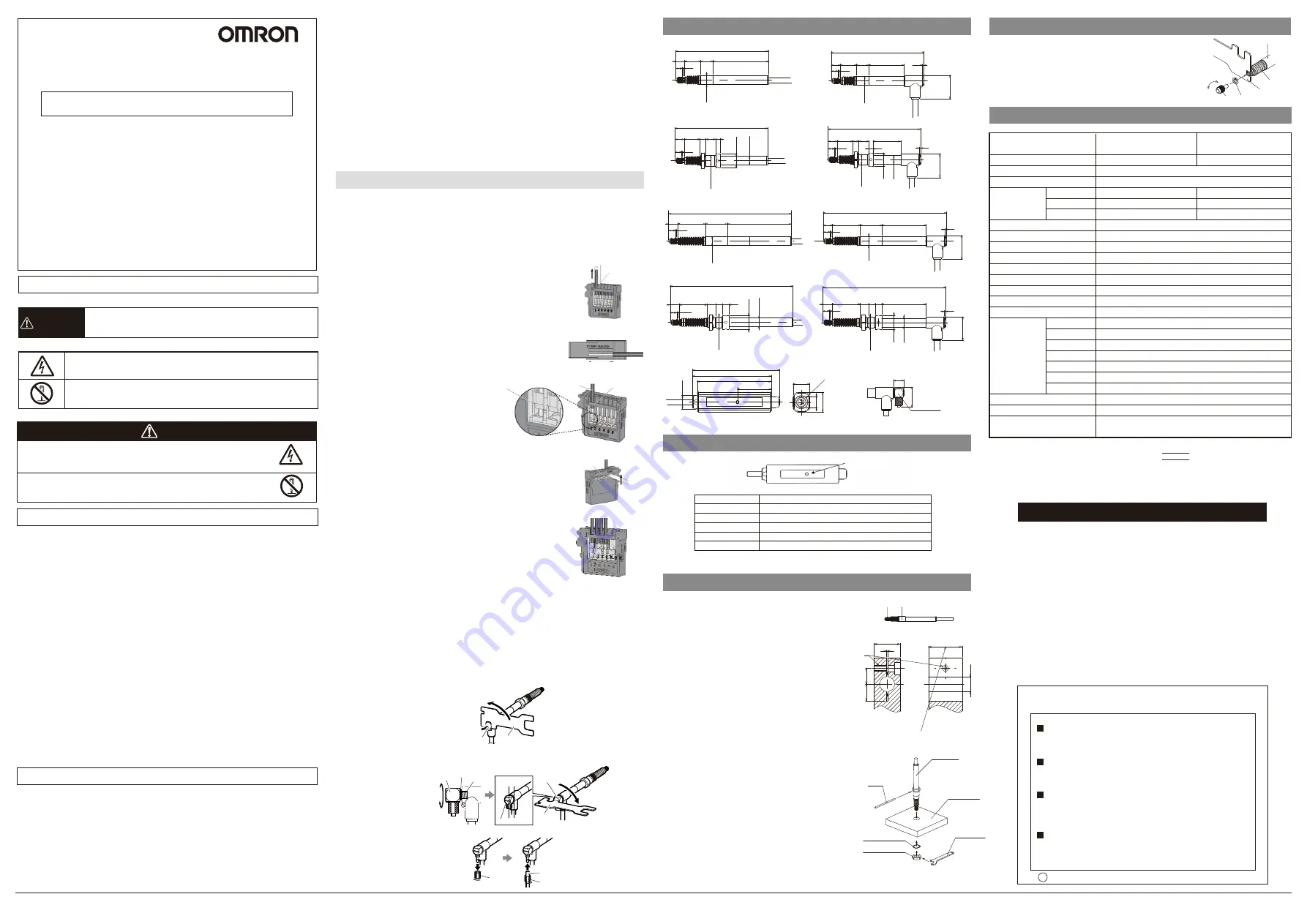
5. Specifications
1. Dimensions
2
.
Display of preamplifier block
3. Installing Heads
E9NC-TH
□□
Series
・
The suction air must be dry air with a negative pressure of 0.04 to 0.067 MPa.
・
The outside diameter of the tube for air suction inlet must be 4 mm.
・
Air suction draws the spindle in.
・
If the spindle extrusion rate is high, the amplifier indication may display an error when
a workpiece is contacted.
・
Too much impact may shift the ball retainer inside the bearing, resulting in less
operating range. If so, adjust the spindle rate.
■
Using air supply
(E9NC-TH5L/E9NC-TH5LF/E9NC-TH12L/E9NC-TH12LF)
■
Installation
Model
Measuring range(Moving range)
Resolution
Precision (at 20 °
C)
Measuring force
(at 20 °C)
Ambient temperature
Ambient humidity
Maximum response speed
Origin detection speed
Origin position
Degree of protection
Vibration resistance
Shock resistance
Number of sliding
Material
Weight (packed state/main unit only)
Probe
Accessories
Head
Probe
Rubber boot
Cable
Preamplifier
Tightening nut
Wave washer
Set upward
Set horizontal
Set downward
E9NC-TH5S/E9NC-TH5SF
E9NC-TH5L/E9NC-TH5LF
5mm
0.1μm
1μm
0.35±0.25N
0.4±0.25N
0.45±0.25N
Operating: -10 to 55°C, storage: -20 to 60°C (with no icing or condensation)
Operating and storage: 35% to 85% (with no condensation)
80m/min
80m/min
1±0.5 mm from the lowest point of spindle extrusion position
Head: *1, Preamplifier: IEC IP40
100m/s
2
(20〜2000Hz) 20 min each in X, Y, and Z directions
1000m/s
2
3 times each in X, Y, and Z directions
92 million times (based on Omron's dedicated evaluation)
SUS303
Carbide
NBR
PVC
ABS
SUS410 (E9NC-TH□□F only)
SK5 (E9NC-TH□□F only)
Approx. 340g/approx. 110g
With spherical surface of carbide, thread size of M2.5
Instruction Sheet, Wrench, Hose elbow(E9NC-TH□L□)
Accessory for flanged model only(E9NC-TH□□F)*1
E9NC-TH12S/E9NC-TH12SF
E9NC-TH12L/E9NC-TH12LF
12mm
0.4±0.3N
0.5±0.3N
0.6±0.3N
4
.
Attaching the probe
・
Use the dedicated wrench that comes with the product for attaching
and detaching the probe. Do not apply torque of 0.1 N
・
m or more to
the spindle during the task. Otherwise damage may result.
・
Unless you use a flat probe, it is recommended to use the accessory
spring washer of nominal 2.5 or screw lock to prevent the probe to
loosen. (Reference tightening torque value: 0.05 to 0.06 N
・
m)
<Straight Model>
(
E9NC-TH5S/E9NC-TH5
L
/E9NC-TH12S/E9NC-TH12L
)
・
Mounting head, be sure to grab the stem.
・
To attach the head to other equipment, avoid securing it on a
position where a screw directly contacts this product.
・
As this product uses a ball bearing, tightening the stem too much
could damage the measurement axis, resulting in crippled
movement.
・
To attach it to equipment using a holder, use the <recommended
mounting jig> with specified tightening torque of 0.6 N
・
m to
secure.
・
Attach the stem so that the slotted block should be tightened by
the screw. Never attach the stem by cutting screw thread in the
Ø
8 mm hole and by screwing the stem with a setscrew. Or sliding
movement or precision may be degraded.
<Flanged Model>
(E9NC-TH5SF/E9NC-TH5LF/E9NC-TH12SF/E9NC-TH12LF)
・
Recommended diameter of the hole to attach the head is
Ø
9.7
±
0.15 mm.
・
The mounting plate thicknesses are shown below:
E9NC-TH5SF/E9NC-TH5LF: 9 to 11 mm
E9NC-TH12SF/E9NC-TH12LF: 7 to 11 mm
・
To attach the head, always use the accessory tightening nut,
wave washer, clamp spanner, and pin that come with the product.
The tightening torque shall be applied so that the wave washer
should be completely flat.
Recommended tightening torque: 1.0 N
・
m
Maximum tightening torque: 2.0 N
・
m
ATTENTION
・
To prevent cables to cut, fix it in a proper place. Avoid pulling
cables too strongly or bending them too much.
・
The degree of parallelization affects the precision of detection.
Use the mounting bracket (or sleeve) so that it should be kept
within 0.3 mm for 100 mm of movement.
・
Do not apply force to rotation direction after securing the stem.
Or it may be damaged.
Unit: mm
E9NC-TH12S
E9NC-TH12LF
E9NC-TH12SF
Cable length between head and
preamplifier: 2 m(φ4.8)
Attaching the hose elbow
E9NC-TH12L
E9NC-TH5S
E9NC-TH5L
E9NC-TH5SF
E9NC-TH5LF
Cap
Dedicated wrench
Dedicated
wrench
Hose elbow
Tighten to parallel
position
Hose elbow
M5 screw
Gasket
Hose elbow
Ø
4 mm tube
Securing ring
Securing ring
6
0.6
8.1 14.2
11
49.5
(82.8)
Ø
8
-
0 0.009
(82.7)
0.6
8.1 14.2
11
31.6
6
21
Ø
8
- 00.009
1.3
(82.8)
6
0.6
8.1 14.2 5.3 8.7 4
Ø
9.5
-
0 0.009
Ø
12
Ø
7.9
0.6
6
8.1 14.2 5.3 8.7
4
24.6
(82.7)
Ø
9.5
- 00.009
Ø
7.9
Ø
12
21
1.3
(109.7)
6
0.6
8.1
Ø
8
-
0 0.009
19.5
57.2
24.9
6
0.6
8.1
24.9
19.5
39.3
(109.6)
Ø
8
- 00.009
21
1.3
6
0.6
8.1
24.9
8 5.8
5.7
Ø
9.5
-
0 0.009
Ø
12
Ø
7.9
(109.7)
6
0.6
8.1
24.9
8 5.8 5.7
39.3
(109.6)
Ø
9.5
- 00.009
Ø
12
Ø
7.9
21
1.3
(9.2)
(17.5)
Hose elbow
LED Indication Status
Meanings
Off
Non-energized
Flashing blue
Energized, origin point not passed yet, or origin point detecting
Blue light ON
Energized, origin point detected (with origin point use setting ON)
Red light ON
Head speed error
Flashing red
Head circuit failure
+0.014 +0.005
Tightening Torque: 0.6 N・m
Material: SUS303
Unit: mm
1
14
8.5
9
M3
Ø
8
G6
Probe Stem
<Recommended Mounting Jig>
Head
Mounting Plate
Pin
Clamp spanner
Wave washer
Tightening nut
Stem
Spindle
Dedicated
wrench
(Spindle fixation)
Probe Washer
1. Remove the cap.
3. Attach
Ø
4 mm tube.
2. Attach the hose elbow.
Manually tighten the M5 screw until the gasket contacts the wall. Then use the
dedicated wrench to tighten by 90°.
*1. E9NC-TH□L□ When using the hose elbow
IEC IP67
E9NC-TH□L□ When not using the hose elbow
E9NC-TH□S□
*2. Clamp wrench, Pin, Tightening nut, Wave washer
Operation Indicator
Do not forcibly bend or pull the cables.
Do not put a heavy object on them or heat them.
Doing so may damage the cables, resulting in a fire.
Do not disassemble or alter the unit. There is a risk of
injury or electric shock. And it may cause damage on the
internal circuit.
●
Warning: Electric Shock
Indicates a risk of electric shock under certain conditions.
WARNING
●
Resolution prohibition
Indicates prohibition when there is a risk of minor injury from electrical
shock or other source if the product is disassembled.
©
OMRON Corporation 2013 All Rights Reserved.
INSTRUCTION SHEET
Model
E9NC-TH
□□
Series
Contact-Type Smart Head (Detection Type)
PRECAUTIONS ON SAFETY
●
Keys to Warning Symbols
●
Alert Statements
●
Explanation of signs
Indicates a potentially hazardous situation which, if not avoided, will
result in minor or moderate injury, or may result in serious injury or
death. Additionally there may be significant property damage.
WARNING
Thank you for selecting OMRON product. This sheet primarily describes
precautions required in installing and operating the product. Before operating
the product, read the sheet thoroughly to acquire sufficient knowledge of
the product. For your convenience, keep the sheet at your disposal.
Refer to the user’s manual for details.
The following notice applies only to products that carry the CE mark:
Notice:
This is a class A product. In residential areas it may cause radio
interference, in which case the user may be required to take adequate
measures to reduce interference.
Manufacturer:
Omron Corporation,
Shiokoji Horikawa, Shimogyo-ku,
Kyoto 600-8530 JAPAN
TRACEABILITY INFORMATION:
Importer in EU:
Omron Europe B.V.
Wegalaan 67-69
2132 JD Hoofddorp,
The Netherlands
PRECAUTIONS FOR SAFE USE
Please observe the following precautions for safe use of the products.
(1)Installation Environment
・
Do not use the product in environments where it can be exposed to inflammable/explosive gas.
・
To secure the safety of operation and maintenance, do not install the product close to
high-voltage devices and power devices.
(2)Power Supply and Wiring
・
Be sure to use a dedicated amplifier unit (E9NC-TA
□□
). Connecting to other amplifier unit
may cause damage or fire.
・
When shortening cables, be sure to connect wires according to the specifications.
Misconnection may cause damage or fire.
・
High-Voltage lines and power lines must be wired separately from this product. Wiring them
together or placing them in the same duct may cause induction, resulting in malfunction or damage.
・
Always turn off the power of the unit before connecting or disconnecting cables.
・
To prevent cables to cut, fix it in a place where too much tension should not be applied to it.
Avoid pulling cables too strongly or bending them too much.
Repeated flexing: R50 or more
Permanent bend: R20 or more
・
Head and output cables must be placed separately from the power line.
(3)Installation
・
Use screws or tightening nut for mounting and be sure to tighten screws with a specified torque.
Specified torque: M3 screw:0.6N
・
m Tightening nut:1.0N
・
m
(4)Applicable
standards
・
EN61326-1
・
Electromagnetic environment : Industrial electromagnetic environment
(EN/IEC
61326-1
Table 2)
(5)Other Rules
・
Do not attempt to disassemble, deform by pressure, incinerate, repair, or modify this product.
・
When disposing of the product, treat as industrial waste.
・
If you notice an abnormal condition such as a strange odor, extreme heating of the unit, or
smoke, immediately stop using the product, turn off the power, and consult your dealer.
PRECAUTIONS FOR CORRECT USE
Please observe the following precautions to prevent failure to operate, malfunctions, or
undesirable effects on product performance.
(1)Do not install the product in locations subjected to the following conditions:
・
Surrounding air temperature outside the rating
・
Rapid temperature fluctuations (causing condensation)
・
Relative humidity outside the range of 35 to 85%
・
Presence of corrosive or flammable gases
・
Presence of dust, salt, or iron particles
・
Direct vibration or shock
・
Water, oil, or chemical fumes or spray, or mist atmospheres
・
Presence of intense magnetic, electric field or high frequency electric field (use the product in
a place distant from a noise source such as high power relay and high-voltage high-current
switch by 0.5 m or more)
(2)Warming up
・
The circuitry is not stable immediately after turning the power ON, and the values gradually
change until the Sensor Head is completely warmed up.
・
Before using the product, check that its functionality and capability are normal.
(3)Maintenance and inspection
・
Always turn off the power of the unit before connecting or disconnecting cables.
・
Do not use thinner, alcohol, benzene, acetone, or kerosene to clean the sensor.
・
If oil that becomes extremely viscous when it's dry, such as cutting oil, attaches to the rubber
boot, the operation may not work properly.
Wipe off with a waste cloth dampened with absolute alcohol.
・
The rubber boot may be significantly degraded by organic solvent or ozone in the air or
ultraviolet rays in the environment. In such cases, replace the rubber boot regularly (6 months to
a year).
・
Rubber boots are coated with grease. Please do not remove the grease when the rubber boot is
used, since sliding movement may be degraded if it is removed.
・
When it used after wiping off the oil, perform regular maintenance not to rust. Be sure to check
that there is no influence on the measurement due to the oil when it is used with the oil.
■
Do not use this product under water, rain or outdoors.
Push the operation lever at the operation slot with the slotted
screwdriver and pull out the wire to adjust the cable length.
The tip of the screwdriver must be 2 mm or less. The type of
screwdriver whose tip width becomes broaden toward its root
cannot be used.
■
Shortening the connection cable for use
■
Shortening the connection cable for use
(3) Push the slotted screwdriver all the way to the releasing slot
and pry the slotted screwdriver up and down lightly. When you
feel a click on the slotted screwdriver, pry it to the reverse
direction of the wire insertion direction. The operation lever will
recover with a click sound.
(4) Check that the operation lever recovers and the wire coating
enters into the wire insertion slot. The shield wire cover must
not be shorted circuited. (The wires are connected when you
pull the wire and feel a resistance.)
(1) According to "STRIP GAUGE" shown on the side of the
product, strip the coating of the shield for 20 mm or less, strip
the coating of the core wire for 7 to 8 mm, and twist the wire
for several times.
(2) Insert the wire all the way to the wire
insertion slot. Make sure that the wire coating
is located inside the wire insertion slot and
the tip of the conductor passes through the
connection part. Connect wires as follows.
Terminal No.1: Brown, No.2: Shield, No.3:
White, No.4: Red.
■
Procedure to connect the connector
Operation lever (White)
7 to 8 mm
Connecting part
Wire coating
Wire insertion port
Operation lever
(White)
Release port
66
70
(77.25)
(Ø12)
(30)
15
10 18
11.5Dia
Suitability for Use
s
Omron Companies shall not be responsible for conformity with any standards,
codes or regulations which apply to the combination of the Product in the
Buyer’s application or use of the Product. At Buyer’s request, Omron will
provide applicable third party certification documents identifying ratings and
limitations of use which apply to the Product. This information by itself is not
sufficient for a complete determination of the suitability of the Product in
combination with the end product, machine, system, or other application or
use. Buyer shall be solely responsible for determining appropriateness of the
particular Product with respect to Buyer’s application, product or system.
Buyer shall take application responsibility in all cases.
NEVER USE THE PRODUCT FOR AN APPLICATION INVOLVING
SERIOUS RISK TO LIFE OR PROPERTY WITHOUT ENSURING THAT THE
SYSTEM AS A WHOLE HAS BEEN DESIGNED TO ADDRESS THE RISKS,
AND THAT THE OMRON PRODUCT(S) IS PROPERLY RATED AND
INSTALLED FOR THE INTENDED USE WITHIN THE OVERALL
EQUIPMENT OR SYSTEM.
See also Product catalog for Warranty and Limitation of Liability.
Oct, 2014
D
OMRON Corporation
Industrial Automation Company
Contact: www.ia.omron.com
Tokyo, JAPAN
OMRON ELECTRONICS LLC
2895 Greenspoint Parkway, Suite 200
Hoffman Estates, IL 60169 U.S.A.
Tel: (1) 847-843-7900/Fax: (1) 847-843-7787
OMRON ASIA PACIFIC PTE. LTD.
No. 438A Alexandra Road # 05-05/08 (Lobby 2),
Alexandra Technopark,
Singapore 119967
Tel: (65) 6835-3011/Fax: (65) 6835-2711
OMRON (CHINA) CO., LTD.
Room 2211, Bank of China Tower,
200 Yin Cheng Zhong Road,
PuDong New Area, Shanghai, 200120, China
Tel: (86) 21-5037-2222/Fax: (86) 21-5037-2200
OMRON EUROPE B.V.
Sensor Business Unit
Carl-Benz-Str. 4, D-71154 Nufringen, Germany
Tel: (49) 7032-811-0/Fax: (49) 7032-811-199
Regional Headquarters
8
(Using E9NC-TH5□)
18
(UsingE9NC-TH12□)


