


E2EM
E2EM
11
Designing
Confirmation of Connection between DC 2-wire Proximity
Sensor and Programmable Controller
Connection conditions are determined from the relationship be-
tween the input ON voltage and OFF voltage of the PC and the out-
put residual voltage and leakage current of the Proximity Sensor.
Connection Conditions
1. Relationship between the ON voltage of the PC and the
residual voltage of the Proximity Sensor must be as follows:
V
on
x
V
cc
– V
R
V
on
: ON voltage of the PC
V
cc
: Supply voltage
V
R
: Output residual voltage the Proximity Sensor
2. Relationship between the OFF voltage of the PC and the
leakage current of the Proximity Sensor must be as follows:
V
off
y
I
leak
x R
in
V
off
: OFF voltage of the PC
I
leak
: Leakage current of the Proximity Sensor
R
in
: Input impedance of the PC
Connection is possible under the following conditions.
Example values on the PC side
ON voltage: 10.2 V min.
OFF voltage: 3 V max.
Input impedance: 3.5 k
Ω
Example values on the Proximity Sensor side
Output residual voltage: 5 V max.
Leakage current: 0.8 mA max.
If these values are put in the above formula, V
on
and V
off
will be as
follows:
V
on
: 10.2 V
t
24 V–5 V (=19 V)
V
off
: 3 V
u
0.8 mA x 3.5 k
Ω
(=2.8 V)
Wiring
High-tension Lines
Wiring through Metal Conduit:
If there is a power or high-tension line near the cable of the Proximity
Sensor, wire the cable through an independent metal conduit to pre-
vent against Proximity Sensor damage or malfunctioning.
Connections
DC 2-wire Models
Connection to relay load
Brown
Blue
24 VDC
Note:
The residual voltage of the DC 2-wire model is 5 V. Check
the operating voltage of the relay.
DC 3-wire Models
Connection to S3D2 Sensor Controller
Operation can be reversed by selecting the signal input selec-
tor of the S3D2.
Blue 0 V
Black OUT
Brown +12 V
S3D2
Cable Extension
Standard cable length is less than 200 m.
The tractive force is 50 N.
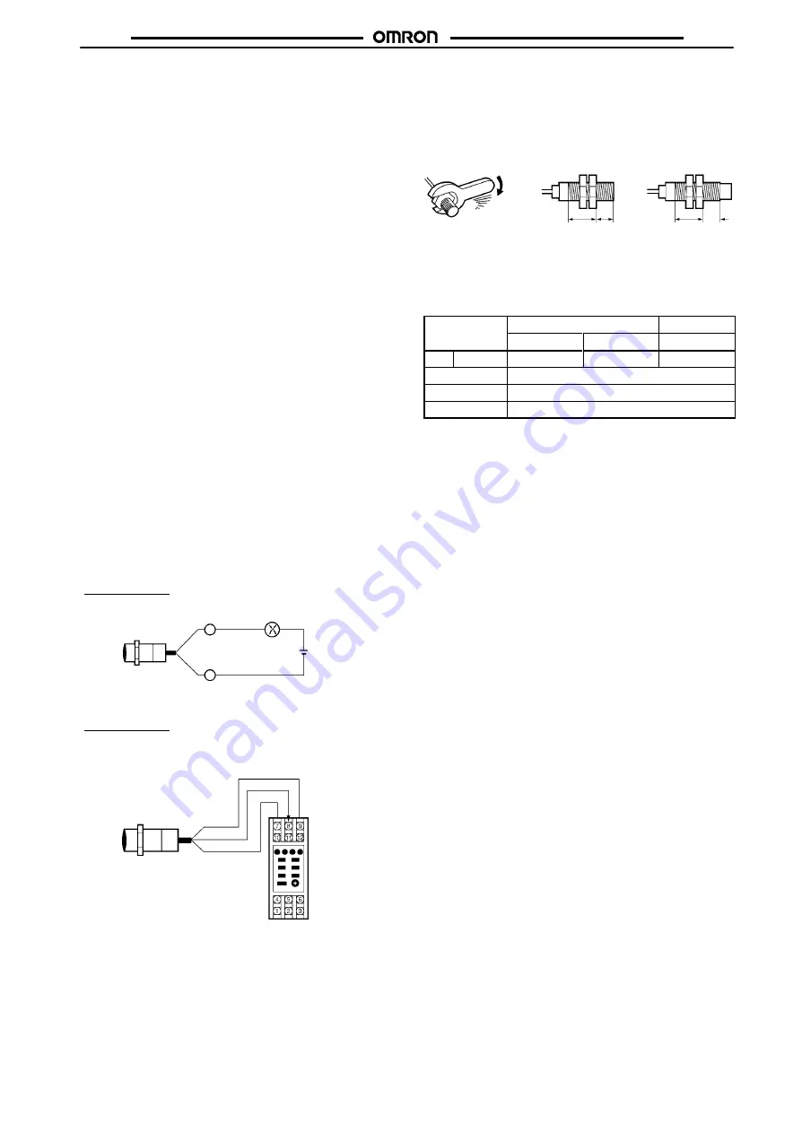
Mounting
The Proximity Sensor must not be subjected to excessive shock
with a hammer when it is installed, otherwise the Proximity Sensor
may be damaged or lose its water-resistivity.
Do not tighten the nut with excessive force. A washer must be used
with the nut.
Shielded Model
Unshielded Model
Part B Part A
Part B Part A
Note:
The table below shows the tightening torques for part A and
part B nuts. In the previous examples, the nut is on the sen-
sor head side (part B) and hence the tightening torque for
part B applies. If this nut is in part A, the tightening torque for
part A applies instead.
Type
Part A
Part B
Length
Torque
Torque
M8
Shielded
9 mm
9 N
S
m
12 N
S
m
M12
30 N
S
m
M18
70 N
S
m
M30
180 N
S
m
Maintenance and Inspection
Periodically perform the following checks to ensure stable operation
of the Proximity Sensor over a long period of time.
1. Check for mounting position, dislocation, looseness, or
distortion of the Proximity Sensor and sensing objects.
2. Check for loose wiring and connections, improper contacts,
and line breakage.
3. Check for attachment or accumulation of metal powder or
dust.
4. Check for abnormal temperature conditions and other
environmental conditions.
5. Check for proper lighting of indicators (for models with a set
indicator.)
Never disassemble or repair the Sensor.
Environment
Water Resistivity
Do not use the Proximity Sensor underwater, outdoors, or in the
rain.
Operating Environment
Be sure to use the Proximity Sensor within its operating ambient
temperature range and do not use the Proximity Sensor outdoors so
that its reliability and life expectancy can be maintained. Although
the Proximity Sensor is water resistive, a cover to protect the Prox-
imity Sensor from water or water-soluble machining oil is recom-
mended so that its reliability and life expectancy can be maintained.
Do not use the Proximity Sensor in an environment with chemical
gas (e.g., strong alkaline or acid gasses including nitric, chromic,
and concentrated sulfuric acid gases).
Connecting Load to DC 2-wire Sensor
Refer to the following before using DC 2-wire Proximity Sensors.
Surge Protection
Although the Proximity Sensor has a surge absorption circuit, if
there is any machine that has a large surge current (e.g., a motor or
welding machine) near the Proximity Sensor, connect a surge sup-
pressor to the machine.


