background image

LCD Digital Operator 


LCD Digital Operator User's Manual v0_90 110218.doc 

11 

Issue 0.90 Draft 


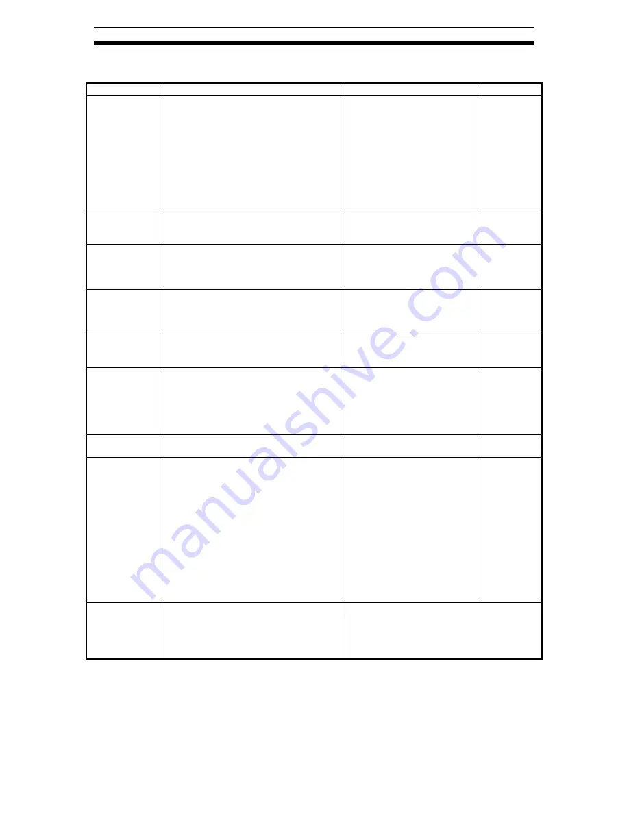
3.3 Details of Option mode 
 

Item 

Content 

Setting range 

Default 

Language 

Setting language 

01: English 
02: Deutsch 
03: Français 
04: Español 
05: Italiano 
06: Português 
07: 

日本語

  (Japanese) 

08: 

中文

  (Chinese) 

09: Türkçe 
10: Pycck

ИЙ


01 

Date and Time 

Setting Date and Time for the LCD 
digital operator 

Date: 2000/1/1~2099/12/31 
Time: 00:00~23:59 
Format 1~3 

2009/01/01 

00:00 

Read Lock 

Set  “Read lock” enable to disable, in 
order to protect the parameter saved in 
LCD digital operator from being 
overwritten. 

01: Enable 
02: Disable 

02 

INV Type 
Select 

Please select the correct INV type 
using LCD digital operator, 
otherwise, ”COM ERROR” will be 
displayed automatically. 

01: Type 1 (MX2, LX) 
02: Type 2 (RX) 

01 

R/W Storage 
Mode 

Sets the number of parameter sets for 
READ/W RITE mode. 
(Refer to chapter 4 for more details.) 

01: Single 
02: Quad 

02 

Backlight 
Auto-Off 

When LCD digital operator remains 
without key operations for 1 minute, 
LCD backlight will be turned off. When 
a key is pressed it will turned on. 
The  Backlight  Auto-Off  function  does 
not work when trip happened. 

01: Off 
02: 1 minute 

01 

Backlight 
Flicker 

The Orange backlight will be enabled 
or disabled.. 

01: Enable 
02: Disable 

01 

Operator 
Reset 

Use  this  function  to  return  t o   default 
settings of LCD digital operator. 
The next items will be reset: 
1)   Language:  English 
2)   Date   and   time:2009/01/01   THU 
00:00 
3)   Time format:  01:YY/MM/DD 
4)   Read lock:  Disable 
5)   R/W Storage Mode:  Quad 
6)   Backlight Auto-Off:  Off 
7)   Backlight Flicker:  Enable 
After this,  date  and   time setting is 
required. 

01: YES 
02: NO 


02 


Check Mode 

Check  if  LED  and  key  etc.  are normal 
or not. 

Key&Led Check, Lcd Check, 
EEPROM Check, RTC 
Check, Serial Loopback, 
Debug Mode, Firmware 
Version. 

 
NOTE: 
Please do not execute the EEPROM check. Otherwise, the data (parameters/EzSQ program) 
saved in LCD digital operator will be erased.

Summary of Contents for AX-OP05-E

Page 1: ...Cat No Ixxx Ex xx X DRAFT V0 90 LCD 5 LINE DIGITAL OPERATOR USER S MANUAL...

Page 2: ...of Option mode 11 3 4 Monitor A Display Mode 12 3 5 Monitor B Display Mode 13 3 6 Function Mode 14 3 7 Trip Mode 15 4 Read Write function and operation 16 4 1 R W Storage Mode Single READ function 16...

Page 3: ...erating this equipment Read the messages and follow these instructions carefully WARNING Indicates a potentially hazardous situation which if not avoided can result in serious injury or death CAUTION...

Page 4: ...emotely via a cable It has the additional capability of reading up to 5 Parameter Sets or a Parameter Set Drive Programming application from the inverter and store into the LCD digital operator memory...

Page 5: ...n operation function is effective by input terminal OPE Press the key more than 2 seconds 6 Key Enabled Led Green Light on only when operation command is set in LCD digital operator 7 LCD Display Plea...

Page 6: ...fter that it jumps to the above layer 6 UP It is used to move up the cursor it increases a function code in 1 or increases a parameter value 7 DOWN It is used to move down the cursor it decreases a fu...

Page 7: ...f LCD Display The first line of LCD monitor always displays the Display Mode the Motor Selected the Inverter RUN Status and the Display Selection Item Content of Display Content MONITOR A Monitor A mo...

Page 8: ...ew 5mm when you install the operator on the control panel Recommended torque is 0 9 1 0 Nm 80 18 40 26 5 2 M3x5 Backside 2 4 Recommended cable Model Content ICS 1 1m cable ICS 3 3m cable ICS 5 5m cabl...

Page 9: ...of each mode is shown as below Monitor Mode A The d group inverter parameters and F U group inverter parameter are displayed on the same screen in this mode The content of d group parameter is display...

Page 10: ...y to select the value to set Press the key to store the new value Press the key to cancel the new value And then 3 The cursor will appear in the second row 2 Date and Time 4 Pressing the key it enters...

Page 11: ...r to chapter 4 for more details 01 Single 02 Quad 02 Backlight Auto Off When LCD digital operator remains without key operations for 1 minute LCD backlight will be turned off When a key is pressed it...

Page 12: ...layed in the Monitor A pressing the key 2 After that use the or key to select the function code to be displayed into the Monitor A Use or key to move the cursor to the function code F001 in this case...

Page 13: ...cursor will appear on the first row of the four d group inverter parameters Use the or key to move between the four Monitor B inverter parameters 3 Pressing the key the cursor will appear on the funct...

Page 14: ...y at the navigation level 2 Pressing the key the cursor will appear in the function code Then use the or key to select the function that will be changed 3 After that pressing the key the cursor will a...

Page 15: ...he key the past trip information 6 trip errors and the warning information 1 time that are recorded on the inverter will be displayed Trip information is composed in two pages For change from page 1 P...

Page 16: ...d immediately after pressing or key After pressing the key in any display mode except Write mode and Option mode the inverter s parameter configuration are read and saved into LCD digital operator EzS...

Page 17: ...he inverter automatically after the parameter copy is finished It will return to the previous display after write function is completed When the inverter does NOT support EzSQ Drive Programming functi...

Page 18: ...am independently In this case LCD digital operator can save four sets of inverter parameters or one set of inverter parameters and one EzSQ Drive Programming program Please note that one EzSQ Drive Pr...

Page 19: ...fter pressing the key the Select data available are 01 Read data 02 Read data EzSQ 03 Verify data 04 Verify EzSQ 05 Cancel NOTE only three selection items 01 03 and 05 are displayed when memory No 2 N...

Page 20: ...90 Draft 4 4 R W Storage Mode Quad VERIFY function With and without EzSQ Drive Programming inverter support The result is shown automatically after the parameter or EzSQ Drive Programming verificatio...

Page 21: ...s Manual v0_90 110218 doc 21 Issue 0 90 Draft 4 5 R W Storage Mode Quad WRITE function When the inverter does NOT support EzSQ Drive Programming function Automatically it will return to previous disp...

Page 22: ...rsor up and down to select the data value to be written After pressing the key the Select data available are 01 Write data 02 Write data EzSQ 03 Cancel NOTE only 01 and 03 items are displayed when mem...

Page 23: ...ng parameter State and setting of the inverter Only parameter Parameter EzSQ Drive Programming Inverter is running EzSQ Drive Programming is running written unable Soft locked b031 Display is limited...

Page 24: ...ator 00 Full display 01 Function specific display 02 User setting 03 Data comparison display 04 Basic display 05 Monitor display b038 Initial screen selection Select the start display 000 Last modifie...

Page 25: ...is running Check if the WRITE key is pressed while soft lock is ON The WRITE key should be pressed only while the inverter stops Release the Soft Lock of the inverter INV in TRIP mode WRITE key is pr...

Page 26: ...wer supply or reset the terminal reset signal YES YES YES YES NO NO NO NO NO The inverter power supply is ON The cable is connected properly to both sides inverter and LCD digital operator The cable i...

Page 27: ...o 5 2 VDC Ambient temperature 10 to 50 degree C Humidity 20 to 90 RH no dew condensation Store temperature 20 to 65 degree C Place to use 1000m or less in height at a place with no corrosion gas and d...

Page 28: ...l operator is turned on Thus the time of Trip mode Read mode and Write mode cannot be displayed correctly unless the time is set properly in Option mode after power supply of LCD digital operator is t...

Reviews: