


!
!
!
!
!
!
!
!
!
!
3G3FV-PPG
j
2
PG Speed Control Card
(For the 3G3FV only)
INSTRUCTION SHEET
Thank you for purchasing this OMRON product. Please read this
instruction sheet and thoroughly familiarize yourself with the func-
tions and characteristics of the product before use. This instruc-
tion sheet describes procedures for mounting and wiring the
3G3FV-PPG
j
2 PG Speed Control Card, and should be read in
conjunction with the 3G3FV Inverter User’s Manual (I516). Please
retain this sheet for future reference.
OMRON Corporation
E
OMRON Corporation 1996
All Rights Reserved
Cat. No. I518-E1-1
Safety Precautions
Before attempting to operate the PG Speed Control Card, be sure to
thoroughly familiarize yourself with the information contained in this
instruction sheet and those of any other applicable equipment, make
sure that you have a working knowledge about the equipment, and
make sure that you are well versed on all safety procedures and pre-
cautionary items in order to ensure the safe and proper use of the
OMRON Inverter and other peripheral devices.
Since diagrams in this instruction sheet may be shown with covers
and protective shielding removed in order to provide more detailed
explanations, make sure that covers and protective shielding are re-
placed as stipulated prior to using the product, and then use the prod-
uct only as outlined in the User’s Manual.
Be sure to contact our sales representative if the product is to be left
in storage for an extended period of time.
Make sure that this instruction sheet and other applicable manuals
are readily available to equipment operators.
Make sure that this instruction sheet is readily available once it is
read.
•
The precautionary items list critical information for safety. Be sure
to heed these items at all times.
•
The following conventions are used to indicate and classify pre-
cautions in this instruction sheet.
DANGER!
Not following a precaution given as a “DAN-
GER” is likely to result in fatal or serious injury.
WARNING
N o t f o l l o w i n g a p r e c a u t i o n g i v e n a s a
“WARNING” may result in fatal or serious injury.
Caution
Not following a precaution given as a “Caution”
can result in injury to people or damage to the
product or system.
Items listed under caution may also have serious consequences de-
pending on the circumstances, so be sure to heed these items at all
times.
Mounting
WARNING
Never reach inside the Inverter as this may
result in an electrical shock.
WARNING
Do not mount, remove, or wire Optional Cards
without first shutting the Inverter power OFF and
waiting until the prescribed amount of time
(indicated on the front cover of the Inverter) has
passed after all indicators on the Inverter are no
longer lit. Failure to do so may result in an
electrical shock.
WARNING
Do not nick, apply undue stress, place heavy
objects on, or sandwich cables. Otherwise, this
may result in an electrical shock.
Caution
Do not touch the elements of Optional Cards.
Otherwise, this may result in injury due to elec-
trical shock.
Connections and Settings
Caution
Do not change settings unless absolutely nec-
essary. Otherwise, this will result in injury or
equipment damage.
Caution
Do not mount or remove an Optional Card with
Inverter power ON. Otherwise, this will result in
injury or equipment damage.
Caution
Be sure to connect the ground wire (E) of
Optional Cards. Otherwise, this may result in
equipment damage or faulty operation due to
noise.
Description
The 3G3FV-PPG
j
2 PG Speed Control Card is an Optional Card
used only with the SYSDRIVE 3G3FV Inverter.
This Optional Card controls motor speed and feeds back speed in-
formation to the Inverter from pulse generators (speed detectors,
such as encoders and pulse generators).
The Card is mounted on a 3G3FV Inverter control circuit board.
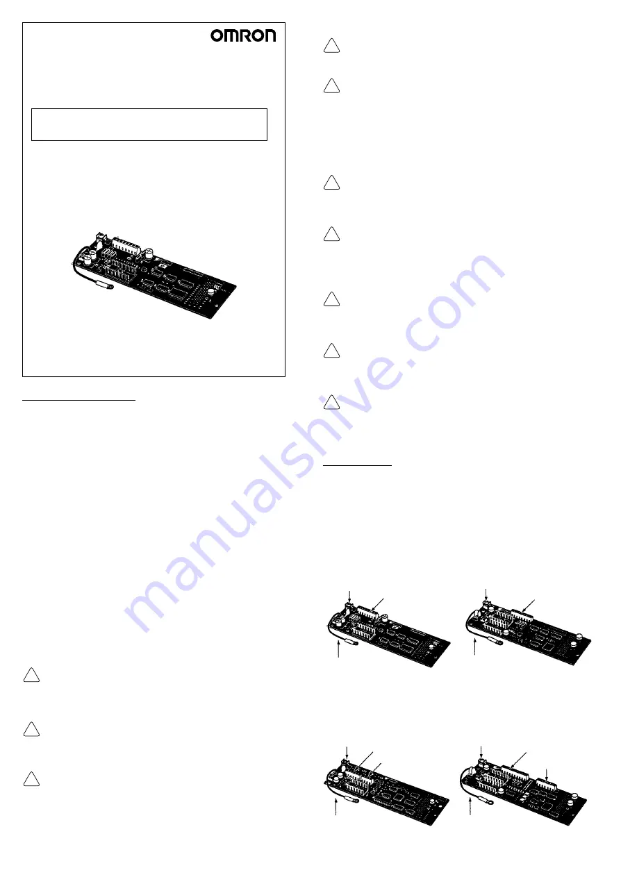
Nomenclature
•
3G3FV-PPGA2
•
3G3FV-PPGD2
TA2 shielded-wire connec-
tion terminal: Shielded wire
connection for an input wire
TA1 I/O terminal
Ground wire E
Connects to the 12 (G)
terminal of the control
circuit board.
TA2 shielded-wire connec-
tion terminal: Shielded wire
connection for an input wire
TA1 I/O terminal
Ground wire E
Connects to the 12 (G)
terminal of the control
circuit board.
•
3G3FV-PPGB2
•
3G3FV-PPGX2
TA3 shielded-wire connec-
tion terminal: Shielded wire
connection for an input wire
TA1 input terminal
Ground wire E
Connects to the 12 (G)
terminal of the control
circuit board.
TA3 shielded-wire connec-
tion terminal: Shielded wire
connection for an input wire
TA1 input terminal
Ground wire E
Connects to the 12 (G)
terminal of the control
circuit board.
TA2 output
terminal
TA2 output
terminal


