© 2011 Omnicell, Inc.
1-, 2-, 3-Cell Color Touch Installation and Service Guide/
67-2014 Rev G
CT PC Box Parts
1-17
Color Touch PC Box
4. Prepare the PowerCom2 CT PC Box for return.
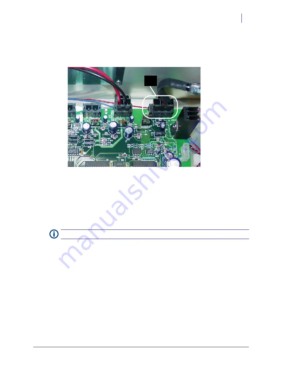
a. Unplug the battery from J5 on the PowerCom2 board.
National Transportation Safety Board (NTSB) regulations prohibit an uninterrupted power
supply (UPS) from being connected during transport.
Figure 1-24.
Location of battery cable on motherboard of PowerCom2 CT PC Box
b. Replace and lock the top cover.
c. Once the PowerCom3 CT PC Box has been removed from the shipping box and installed in
the cabinet, place the PowerCom2 CT PC Box in the shipping box and secure it for return.
Installation Preparation
The PowerCom3 CT PC box is lighter than the PowerCom2 box and does not require two people
for installation and/or removal.
1. Unlock the PowerCom3 CT PC Box top cover with the cam lock key #2036.
2. Lift the front cover and slide it forward to remove.
Battery
Cable
Note:
Follow ESD safety procedures. Always wear an ESD strap when working with electronic components.


