WMS-16 Weather Station Operator’s Manual
5
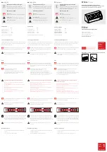
Sensor Installation
Install the sensors in their chosen locations, bearing in mind
the installation considerations noted earlier. Run cables from
the sensors to the control module location, with no cable
exceeding the maximum allowable length listed in Table 1.
When the sensors have been installed and the cables run,
connect and test them as described in the following sections.
Refer to Figure 1 for connection locations on the control
module’s terminal strip.
Table 1: Maximum Sensor Cable Lengths
Sensor
Max. Cable Length
Wind
250
(76m)
T/RH
250
(76m)
Rain
900
(275m)
Barometer
10’
(3m)
Solar Radiation
100
(33m)
WMS-16 Module Setup
The WMS-16 Module has been configured at the Omega
factory to work with the following sensors:
1.Wind speed and Direction
2.Barometer
3.Temperature and Relative Humidity
4.Rain Gauge
To verify the sensor setup press “Esc” to go to the main menu.
Then select item 1. Station setup. From the Setup Menu select
6. Add or remove sensors. Press “Y” to continue. The sensor
configuration page will appear showing all of the presently
enabled sensors. It shows the sensor models and calibration
factors.
Omega WMS-16 Modular Weather Station
© Omega 2000
Sensor Configuration
Sensor Type Model Input Calibration
1.Wind Speed
WMS-01/02
P1
2.Precipitation
All Models
P3
0.0100
3.Pressure
WMS16-BP
A2
4.Humidity
225-050Y(U)/40 A4
5.Temperature
WMS-16T
A5
6.Temperature
WMS-16T
A6
7.Wind Direction WMS-02
A7
Add sensor [A], delete sensor [D], or quit [Q]:
The instructions in Appendix 1 direct you through the
enabling procedure for each type of sensor should any sensor
that you plan to use not be enabled.
Wind Speed and Direction
Wire the wind sensor’s signal cable into the terminal strip on
the control module’s rear panel as shown in Figure 1. Call up
the main screen (Figure 3.) on the display terminal by pressing
“Esc” for main menu. Press “2” for Current Observations at
the main menu. Then press “1” for observation display
(Figure 4).
Turn the Anemometer cups by hand and note the wind speed
displayed on the screen. This value should change as you spin
the cups.
Turn the wind vane so that the tip is aligned with the two
vertically positioned set screws on the base of the sensor. The
wind direction shown on the screen should indicate North (0°).
Turn the vane in increments around the full 360°, noting the
change in the wind direction readings. These should agree
with the present position of the vane.
© Omega 2000
Main Menu
1. Station setup
2. Current observations
3. Display log by hours
4. Display log by days
5. Data download
6. Clear logging memory
Enter your selection (1-6):
Figure 3 Main Screen
Barometric Pressure Module
Wire the three wires of the barometric pressure module into
the terminal strip on the WMS-16 module as shown in Figure
1.
Since pressure varies with elevation, the barometric pressure
sensor must be adjusted to read correctly at the elevations at
which it is installed. This is done using the offset adjustment
screw located on the side of the barometric pressure module.