Page - 20
Page - 21
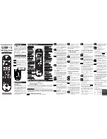
Yellow - (+) Alarm Ignition Control
Blue - Sensor Trigger Loop
White - Accessory (-) Pulse
Brown - OEM Alarm Disarm (-) Pulse
Blue - Sensor Trigger Loop
Auxiliary Harness Connections -
Violet - (+) Brake Input
Green - (-) Hood Safety Switch
Orange - Tach Input
Pink - (-) Activation Trigger
Gray - Glow Plug Input
Auxiliary Harness Connections -
Main Harness Connections -
Black - Negative Chassis Ground
Yellow - Ignition #2
Blue - Ignition #1
Red - Constant 12 Volt Positive
White - Accessory or Exterior Lights
Green - Starter
Black 5-Pin Port-
Auxiliary Receiver
Please See Page 38
Red 3-Pin Port-
Satellite Relays
Please See Page 34
W I R I N G,
C O N T R O L &
A U X I L I A R Y P O R T
O V E R V I E W
Right
(Red)
Control
Button
Diagnostic
LED Light
Left (White)
Control
Button
Override
Switch
Port
Page - 20
Page - 21
Yellow - (+) Alarm Ignition Control
Blue - Sensor Trigger Loop
White - Accessory (-) Pulse
Brown - OEM Alarm Disarm (-) Pulse
Blue - Sensor Trigger Loop
Auxiliary Harness Connections -
Violet - (+) Brake Input
Green - (-) Hood Safety Switch
Orange - Tach Input
Pink - (-) Activation Trigger
Gray - Glow Plug Input
Auxiliary Harness Connections -
Main Harness Connections -
Black - Negative Chassis Ground
Yellow - Ignition #2
Blue - Ignition #1
Red - Constant 12 Volt Positive
White - Accessory or Exterior Lights
Green - Starter
Black 5-Pin Port-
Auxiliary Receiver
Please See Page 38
Red 3-Pin Port-
Satellite Relays
Please See Page 34
W I R I N G,
C O N T R O L &
A U X I L I A R Y P O R T
O V E R V I E W
Right
(Red)
Control
Button
Diagnostic
LED Light
Left (White)
Control
Button
Override
Switch
Port