background image

6

9. Mounting the Flow Meter

The flow meter should be mounted in an easily accessible location so that 
disassembly to clean the measuring elements is easy. Since flow meters 
operate in any installation position and flow direction, you can mount it 
anywhere in your system. When installing the flow meter, make sure that 
liquid remains in the flow meter even at standstill of the system and that the 
flow meter can never run dry. The outlet of the flow meter should always 
have a certain backpressure since this fixes the measuring element of the 
flow meter in the liquid column (the measuring element uses to support itself 
on the liquid column) and the pipeline cannot empty itself. In critical cases, 
or if the pipeline can run empty in standstill or standby mode, it is always 
advisable to install an additional non-return check valve in the outlet line.

Flow meters of the ”FHG“ series can be installed in the pipeline. Always 
select large cross-sections (if possible) for the hydraulic inlet and outlet or 
the entire pipeline system. This reduces the pressure drop and the flow rate 
throughout the system.

Installation Notes

Installation Position

Any, note arrow indicating preferred direction if necessary (calibration ar-
row).Mount the device in such a way that the preamplifier is turned away 
from any potential heat source.
Straight pipe sections are 

not

 required in inlet/outlet.

Connecting Units

If the connecting units (mounting flanges) are to be installed on-site, compli-
ance with the specified torque is required.
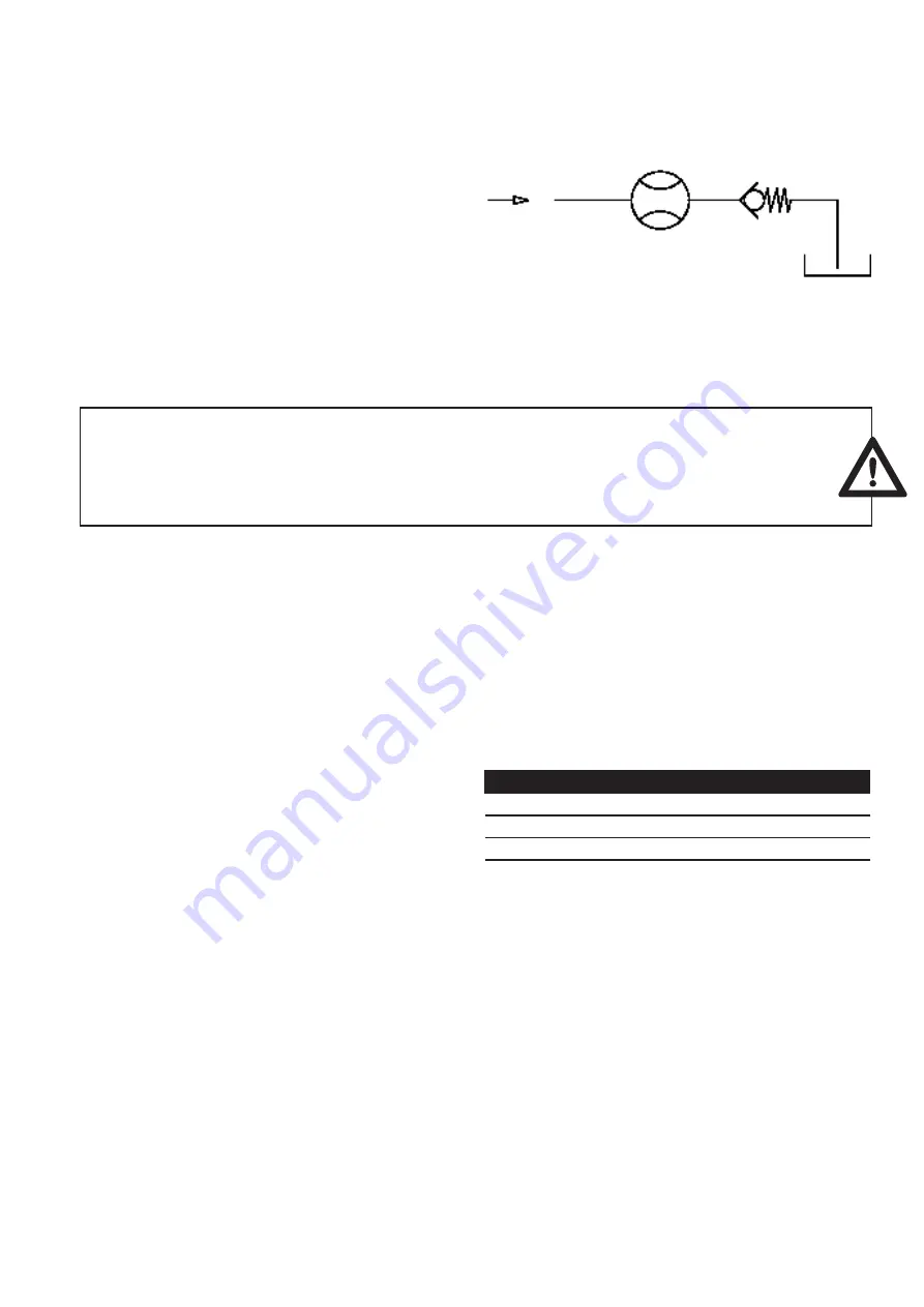
Important:

Make sure that the flow meter measuring elements are always completely filled both 

in inflow and outflow and that the outflow has a little backpressure. This prevents the 

measuring elements from being damaged by a sudden and steep increase of flow and 

at the same time improves measurement accuracy.

Fig. 1: Flow meter with backpressure

Pipe Thread

Please comply with the screw-in depths and sealing systems. PTFE tape or 
liquid sealants such as adhesives are not permitted!

Fastening

The devices must be installed stress-free into the pipeline. This is accomplis-
hed with fastening screws located at the face sides in the connecting units. 
For stress-free assembly, the compressive strength may be limited!

FHG Flow Meter Size

Torque

FHG 1xx2

70 Nm

FHG 1xx4

120 Nm

FHG 1xx5

240 Nm

FHG 1xx7

160 Nm

Table 1: Starting torque of the connection units

10. Cleaning and Flushing of Pipeline before Initial Start-Up

Before initial start-up of the flow meter, you must flush and clean the whole 
system to prevent contaminants from reaching the measuring elements duri-
ng the assembly and installation. Foreign matter or contaminants may block 
the flow meter or severely damage it so that the flow meter readings are no 
longer valid and the device must be returned for repairs. After completion 
of the installation or piping, you must first flush the entire pipeline system 
and carefully clean and flush the tank. This requires that the flow sensor is 
removed from the fluid circuit to flush out all foreign matter or contaminants 
(e.g. chips, metal parts) without problems. Use a rinsing fluid that is compa-
tible with the subsequent used fluid and will not cause adverse reactions.
Such information can be obtained from the supplier or manufacturer of the 
fluid or from Omega. 

Flow meters are sensors manufactured with a high degree of precision. 
They have mechanical measuring elements consisting of two rotors fitted 
into the housing with narrow gaps. Even the smallest damage to the rotors 
causes a measuring error. Always make sure that foreign matter or conta-
minants cannot reach the measuring elements and that the fluid flowing 
through the flow meter is always free of pollutants and particles. Once the 
system is thoroughly flushed and no extraneous material is in the piping sys-
tem, you can mount the flow meter into the fluid circuit and start the actual 
initial startup process.

Non return valve

Flow meter

Tank

Summary of Contents for FHG 100

Page 1: ...omega com e mail info omega com For latest product manuals omegamanual info FHG FLOW METERS Shop online at User sGuide...

Page 2: ...ged by the United Kingdom Office Toll Free 0800 466 342 TEL 33 0 161 37 29 00 FAX 33 0 130 57 54 27 e mail sales omega fr Germany Austria Daimlerstrasse 26 D 75392 Deckenpfronn Germany Toll Free 0 800...

Page 3: ...OPERATING INSTRUCTIONS For FHG Series Flow Meters...

Page 4: ...ics 11 15 Signaling LEDs 12 16 Operating Mode Messages 12 17 Alarm and Warning Messages 13 18 Preamplifier Technical Data 13 19 Preamplifier Pin Assignment 13 20 Maintenance 14 21 Returning for Repair...

Page 5: ...ply them by a high resolution interpolator using adjustable settings The square wave signals are bidirectional and can be utilised by any evaluating instrument as well as computers and PLC controls Th...

Page 6: ...tion check and verify the following properties aspects of the respective circumstances of your system to ensure operation is trouble free safe and reliable 1 The Fluid to be Processed Are the flow met...

Page 7: ...qualify as pressure equipment as defined by Section 1 Paragraph 2 1 4 of the directive listed above and as such are affected by the regulations of this directive Omega flow meters must therefore meet...

Page 8: ...Thread Please comply with the screw in depths and sealing systems PTFE tape or liquid sealants such as adhesives are not permitted Fastening The devices must be installed stress free into the pipeline...

Page 9: ...ply them by a high resolution interpolator using adjustable settings The square wave signals phase shif ted by 90 are bidirectional and can be utilised by any evaluating device as well as computers an...

Page 10: ...surement volume Vm cm3 Imp K Factor Imp l K Factor Imp gal 1 0 10 00000 100 379 2 1 5 00000 200 757 5 2 2 00000 500 1893 10 3 1 00000 1000 3785 25 4 0 40000 2500 9464 32 5 0 31200 3200 12113 50 6 0 20...

Page 11: ...9 FHG 1xx2 FLOW vs FREQUENCY FHG 1xx4 FLOW vs FREQUENCY Flow diagrams vs frequency...

Page 12: ...xample Flow meter FHG 1xx4 Max processable input frequency of the downstream evaluating unit 20 kHz Max operating flow 140 l min Path 1 The diagram yields an IPf of 25 Path 2 IPF fmax x VmIPF1 x 60 Qm...

Page 13: ...ser is able to set the degree of filtering in the form of partial volumes using rotary coding switches Adjustable pulse filtering 0Z 0 25Z 0 5Z 0 75Z 1 0Z 1 25Z 1 5Z 1 75Z 2 0Z 2 25Z 2 5Z 2 75 3 0Z 3...

Page 14: ...fly press the S2 key for the acknowledgment The new pulse rate is enabled a once The rotary coding switch for the pulse filtering has 16 switch settings The degree of filtering is determined with quar...

Page 15: ...tive flow 6 Temperature errors The temperature of the fluid is too high 120 C and may result in flawed or incorrect measurements 18 Preamplifier Technical Data Scanning sensor 2 x GMR sensors in a bri...

Page 16: ...ly well shielded connection cables with a wire cross section of 4 to 5 x 0 25 mm Please note that the housing of the round pin plug is metallic has a connection for the shield and that the potential o...

Page 17: ...flow meter has been completely cleaned and flushed This is to protect our employees and makes our work easier In case of noncompliance with this rule the devices are returned to the sender without att...

Page 18: ...sswiderstand p Durchflusswiderstand p Durchflussbereich 0 bis 50 l min Flow range 0 up to 120 l min Flow range Q Flow range Q Flow range Q Flow range Q Flow range Q Flow range pressure drop p Flow ran...

Page 19: ...sseinheit AR 2500 R Flanschanschlussma e DIN EN 1092 Gewicht 120 kg FHG1xx5 FHG1xx7 Preamplifier Preamplifier Earthing Earthing Weight 81 kg Weight 81 kg Weight 120 kg Sensor module Sensor module Conn...

Page 20: ...ier Preamplifier Earthing Earthing on both sides on both sides M8 15 deep M8 15 deep Weight 12 kg Weight 12 7 kg Weight 24 8 kg Weight 22 kg Sensor module Test Port Test Port Sensor module Connection...

Page 21: ...2 Evaluating unit e g display Flow sensor FHG Q 8l min V 11 53 l direction pos f 424 9 Hz control input 0 voltage blue channel 1 white channel 2 black Error Direction grey 25 Pin Assignment Channel 1...

Page 22: ...therwise shall not exceed the purchase price of the component upon which liability is based In no event shall OMEGA be liable for consequential incidental or special damages CONDITIONS Equipment sold...

Page 23: ...city Indicators Turbine Paddlewheel Systems Totalizers Batch Controllers pH CONDUCTIVITY pH Electrodes Testers Accessories Benchtop Laboratory Meters Controllers Calibrators Simulators Pumps Industria...

Reviews: