background image

13

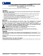
Modbus settings- Routing Diagram

11

DRST-CM lo

cal s

ubm

enu

:

V0R

9

"M

onitor"

SCR

OLL

ING

 HE

LPT

EXTS

:

40.0

0000

(corre

ct)

 N

o

(No)

xxxx

[1]

Set 

corr

ect 

pass

wor

d

%  

 ---OK-->

 --------->

PASS

W.

 ---OK-->

AD

V.SET

 ---OK-->

XXXX

[2]

Ent

er a

dva

nce

d s

etup

 m

enu

?

10.4

mA

[1]

[2]

(Yes)

[x]

[3]

Ent

er L

angu

age

 se

tup

          ^  

o  

V

Ent

er P

ass

wor

d s

etu

p

v    

^

v    

^

|

v    

^

Ent

er S

im

ula

tio

n  m

ode

|

9999

YES

|

Per

for

m P

roc

ess

 ca

libr

atio

n

|

0000

NO

|

Ent

er D

isp

lay

 se

tup

|

|

Per

for

m M

em

ory

 op

era

tio

ns

|

|

MEM

(M

EM

)

Ent

er M

odbu

s s

etu

p

|

             |----

>     

  SE

TUP

  -OK-

|-->

Ent

er R

ota

tio

n s

etu

p

|

[3]

|

[4]

Ena

ble

 m

odbu

s c

omm

unic

atio

n

|

(D

ISP

)

Disa

ble

 M

odbu

s c

omm

unic

atio

n

|

v    

^

     |-->

See

 au

tom

atic

 ba

udra

te 

det

ect

ion

 st

atu

s

|

MEM

|

[5]

Res

et M

odbu

s to

 de

fau

lt?

|

DISP

(C

AL)

[6]

Sel

ect 

Modbu

s s

lav

e a

ddre

ss

|

CAL

     |-->

[7]

Sel

ect 

par

ity

 fo

r M

odbu

s

|

SIM

|

[8]

Sel

ect 

num

ber

 of

 st

op 

bits

|

PASS

(SIM

)

[9]

Sel

ect 

res

pon

se 

del

ay 

in 

ms

|

LAN

G

     |-->

[10

]

Ena

ble

 au

tom

atic

 ba

udra

te 

det

ect

ion

|

MOD

B

|

[11

]

Modbu

s b

aud

rat

e n

ot d

ete

cte

d

|

OR

IEN

(PASS)

Sea

rch

ing

 fo

r M

odbu

s b

aud

rat

e

|


     |-->

Modbu

s b

aud

rat

e d

ete

cte

d

|


|

[12

]

Sel

ect 

baud

rat

e in

 bp

s

|


(LANG)

[13

]

Rot

ate

 de

vic

e up

sid

e d

own

?

|


     |-->

|


|

|


(M

OD

B)

YES

(OFF

)

     |--

>

 ------

-

 ------

-

 ------

-

 ------

-

 ------

-

 ------

-

 -------

     |--

>

MO

D.E

N

 ---OK--

>

 ------

-

 ------

-

 ------

-

 ------

-

 ------

-

 ------

-

 ------

-

 ------

-

 ------

-

 -----

--

 --------->

"M

onitor"

|

[4]

(ON)

 |

^

^

|

|

NO

(Yes)

|

|

|

v    

^

        |----

MO

D.R

ST

 ---OK--

>

----|    


|

 ! ! !  R

eturn

s to

 "M

onitor

" fro

m an

y m

enu, a

fter

 1 

min

 wi

th 

no k

eypre

ss.

|

ON

|

[5]

(No)

 |

|

 ! ! !  R

eturn

s to

 "M

onitor

" upon

 su

cces

ful

 M

odbus 

writ

e c

omm

and.

|

OFF

|

|

247

EVEN

1

20

NO

(Yes)

|

|

STA

TU

S*

1)   

|

v    

^

        |----

AD

R

PAR

ITY

STP

.BI

T

RSP

.D

LY

AUT

O.B

 ---OK--

>

 ------

-

 -------

>

----|    


|

|

YES

^

|   ) o N (

] 0 1 [

] 9 [

] 8 [

] 7 [

] 6 [

|

|

NO

|

|

|

^         v

^         v

^         v

^         v

^         v

|

|

19.2k

|

|

|

247

EVEN

1

1000

YES             

|----

>     

 BA

UD

 OK

 -| 


|

|

|

OD

D

2

|

NO

[12]

|

|

1

NO

NE

0

|

(STA

TUS)

v    

^

|

|

*1)

2400

|

|

SEAR

4800

*1)

|

        |----

 ------

-

 ------

-

 ------

-

 --------->

STA

TUS

 ---OK-->

"M

onitor"

9600

Only 

if au

tom

atic

 baudra

te 

dete

ction

 is

 enabled

|

[11]

19.2k

(OR

IEN

)

NO

38.4k

     |--

>

RO

T.D

EV

 ---OK-->

"M

onitor"

ER

R

57.6k

[13]

SEAR

115.2k

2400

v    

^

4800

YES

9600

NO

19.2k

38.4k

57.6k

115.2k

The

 gra

y s

haded m

enus/t

ext

s are

 onl

y s

hown

 for

 guid

ance

, and

 are

 no

t par

t of


the

 DRST-CM

 spe

cific

 sub

menu

The

 M

odbus 

sub

menu

 is

 lo

cat

ed s

om

ewhere

 in

 the

 m

enu s

tru

cture

 of

 an

y ho

st 

devic

e s

upporting

 DRST-CM

. The

 ac

tual

 pla

ce 

is 

defined

for

 ea

ch 

partic

ular 

devic

e.


Omega A

/S

DRST-CM Lo

cal

 M

enu

.xlsx

Default settings:

Baud rate:  

Parity mode:

Stop bit:  

Address: 

Reponse delay:

19.2 kbps

Even

1

247

0 ms

DRST-CM Modbus settings - Routing Diagram cont.

Summary of Contents for DRST-CM

Page 1: ...e mail info omega com For latest product manuals www omegamanual info DRST CM Communication Enabler TM Shop online at omega com User sGuide ...

Page 2: ...specifications without notice omega com info omega com Servicing North America U S A Omega Engineering Inc Headquarters Toll Free 1 800 826 6342 USA Canada only Customer Service 1 800 622 2378 USA Canada only Engineering Service 1 800 872 9436 USA Canada only Tel 203 359 1660 Fax 203 359 7700 e mail info omega com For Other Locations Visit omega com worldwide ...

Page 3: ...ection 3 Safety Instructions 6 Section 4 Applications 7 Section 5 Technical Characteristics 7 Section 6 Mounting Installation Programming 8 Section 7 Mounting on a DRST device 8 Section 8 Order 8 Section 9 Electrical Specifications 9 10 Section 10 Modbus Parameter settings 11 12 Section 11 Modbus Settings Routing Diagram 13 14 ...

Page 4: ...ction provided by the equipment may be impaired GENERAL WARNING Until the device is fixed do not connect hazardous voltages to the device The following operations should only be carried out on a disconnected device and under ESD safe conditions General mounting connection and disconnection of Modbus cable Troubleshooting the device HAZARD OUS VOLTAGE Triangle with an exclamation mark Read the manu...

Page 5: ...ltages must be carried out according to the specifications of this manual The technician must use tools and instruments that are safe to use Cleaning When disconnected the device may be cleaned with a cloth moistened with distilled water IECEx ATEX installation in Zone 2 IECEx DEK 13 0026 X Ex nA IIC T5 Gc DEKRA 13ATEX0098 X II 3 G Ex nA IIC T5 Gc For safe installation the following must be observ...

Page 6: ... DRST CM display can be used to read the process signal simulate the output signal indicate sensor errors and internal module errors Section 5 Technical Characteristics DRST CM has full DRSL DISPLAY functionality for unit programming process signal monitoring and diagnostics handling Modbus RTU protocol is supported using a serial RS 485 communication wiring Multidrop half duplex connection via sh...

Page 7: ...e LCD dot display Line 1 can e g show the scaled process value Line 2 can e g show the selected engineering unit Line 3 can e g show the analog output or TAG no Line 4 shows status for communication and e g signal trending RJ45 Modbus Connector Pin 5 RS485 A line Pin 4 RS485 B line Pin 8 RS485 GND and shield Section 8 Order Type Description DRST CM DRSL DISPLAY Communication enabler Configmate int...

Page 8: ... response time 50 Hz 20 ms Signal type RS 485 half duplex Serial protocol Modbus RTU Modbus mode RTU slave Devices on an RS485 line Up to 32 without a repeater Data rates baud 2400 4800 9600 19200 38400 57600 115200 Automatic baudrate detection Yes can be configured ON or OFF Parity Even Odd None Stop bit s 1 or 2 Digital adressing 1 247 Response delay 0 1000 ms Approvals EMC 2004 108 EC EN 61326 ...

Page 9: ...ST DRST DRST DRST CM DRST CM IP54 DRST DRST DRST DRST CM DRST CM DRST CM DRST DISPLAY DRST CM DRST CM DRST CM T T T Modbus RTU Zone 2 Cl 1 Div 2 gr A D Safe Area Modbus RTU Gateway Gateway Modbus RTU Ethernet Modbus TCP IP PLC DCS HMI PC PLC DCS HMI PC Modbus RTU PLC DCS HMI PC Access Point ...

Page 10: ...cepted by all slaves but numbers 1 247 are addresses of specific devices With the exception of broadcast messages a slave device always responds to a Modbus message so the master knows the message was received DRST CM Supported Modbus Function Codes The Function Code defines the command that the slave device is to execute such as read data accept data report status Some function codes have subfunc...

Page 11: ...onse delay 0 1000 ms 0 ms default Modbus slave addressing range 1 247 247 default address Modbus Parameter Storage Saved in non volatile memory in the DRST CM device Factory Default Values are marked in bold Modbus RTU segment line termination A 120 Ohm resistor should be installed on both ends of a RS485 Modbus RTU segment loop to prevent signal echoes from corrupting data on the line DRST CM Mod...

Page 12: ...rticular device Omega A S DRST CM Local Menu xlsx DRST CM local submenu V0R9 Monitor SCROLLING HELPTEXTS 40 0 0000 correct No No xxxx 1 Set correct password OK PASSW OK ADV SET OK XXXX 2 Enter advanced setup menu 10 4mA 1 2 Yes x 3 Enter Language setup o V Enter Password setup v v v Enter Simulation mode 9999 YES Perform Process calibration 0000 NO Enter Display setup Perform Memory operations MEM...

Page 13: ...5 No Returns to Monitor upon succesful Modbus write command OFF STATUS 1 v YES NO STATUS 1 Only if automatic baudrate detection is enabled ORIEN NO ROT DEV OK Monitor 13 The gray shaded menus texts are only shown for guidance and are not part of the DRST CM specific submenu The Modbus submenu is located somewhere in the menu structure of any host device supporting DRST CM The actual place is defin...

Page 14: ...GA if the unit is found to be defective it will be repaired or replaced at no charge OMEGA s WARRANTY does not apply to defects resulting from any action of the purchaser including but not limited to mishandling improper interfacing operation outside of design limits improper repair or unauthorized modification This WARRANTY is VOID if the unit shows evidence of having been tampered with or shows ...

Page 15: ...rs M U Turbine Paddlewheel Systems M U Totalizers Batch Controllers pH CONDUCTIVITY M U pH Electrodes Testers Accessories M U Benchtop Laboratory Meters M U Controllers Calibrators Simulators Pumps M U Industrial pH Conductivity Equipment DATA ACQUISITION M U Communications Based Acquisition Systems M U Data Logging Systems M U Wireless Sensors Transmitters Receivers M U Signal Conditioners M U Da...

Reviews: