

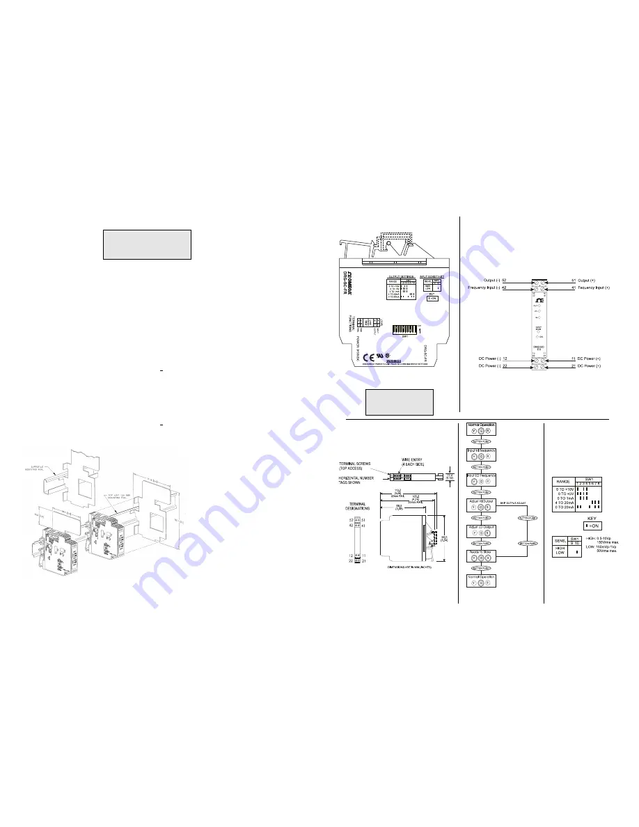
Figure 2: Wiring Diagram for DRG-SC-FR
WARNING: Do not attempt to
change any switch settings with
power applied. Severe damage
may occur!
Figure 1: Factory Calibration;
0 to 1,000Hz, 1Vrms, 4-20mA
Figure 4: DRG-SC-FR Calibration
Flow Chart
Figure 3: Mechanical Dimensions for DRG-SC-FR
Figure 5: Input Sensitivity
Settings (SW1, 9 & 10)
Table 1: Output Switch
Settings (SW1, 1 through 8)
4. Input the maximum desired fre-
quency (if not done already) and
press the CAL button to store. The
yellow INPUT LED should now be the
only LED on.
5. Input the minimum desired fre-
quency and press the CAL button to
store. The green and red LEDs should
now be on.
Note: The most reliable way to input
0Hz is to short circuit the input pins
(42 and 41)
6. To precisely adjust the maximum
output, adjust the input frequency until
the output reads 0.1% of the
maximum selected output range. This
typically occurs near 90% of the HI
input frequency. Press the CAL but-
ton to store the value. The red LED will
now be on.
7. To precisely adjust the minimum
output, lower the input frequency until
the output reads 0.1% of the
minimum selected ouput. This typi-
cally occurs near 10% of the HI input
frequency. Press the CAL button to
store the value. The yellow and Red
LEDs should be on. The green LED
should be dim.
WARNING: Do not attempt to
change any DIP SWITCH settings
for the output (SW1) while power is
applied. Severe damage will result!
Note1: All DRG series modues are designed and tested to operate in ambient temperatures from 0
to 55
°
C, when mounted on a
horizontal DIN rail. When five or more modules are mounted on a vertical rail, circulating air or model DGR-HS01 Heat Sink is
recommended.
CALIBRATION
1. After configuring the DIP switches,
connect the input to a calibrated
frequency source. Connect the out-
put to the actual device load (or a load
approximately equivalent to the ac-
tual device load value) and apply
power (see wiring diagram, Figure
2).
Note: To maximize thermal stability,
final calibration should be performed
in th operating installation, allowing
approximately 1 to 2 hours for warm
up and thermal equilibrium of the
system.
2. Adjust the input frequency to the
desired maximum and observe that
the green LEVEL LED increase in-
tensity as the frequency is increased.
If this is not observed, turn the sensi-
tivity potentiometer in a counter clock-
wise direction until the green LEVEL
LED varies with frequency.
Note: The LEVEL LED may not ap-
pear to be on, if the new range is less
than 10% of the previously cali-
brated range.
3. With the green LED illuminated
press the CAL button once to enter
the calibration mode. The yellow and
green LEDs should now be on.
8. Press the CAL button one final time
to exit the calibration mode. The
green LED should now be on and its
intensity should increase with an in-
creasing input frequency.
9. Check the minimum and maximum
input to output calibration. Repeat
steps 1 through 8 if calibration is not
within desired specifications.
Note 1: To skip Steps 6 and 7 (output
adjustment), press CAL button two
times after Step 5.
Note 2: Removing power to the unit at
any time prior to Step 8 will restore
previous settings and calibration.
OPTIMAL SENSITIVITY
If the amplitudes of the input fre-
quency is within the sensitivity param-
eters (i.e. 150mVp - 1Vp for LO and
0.5Vp - 10Vp for HI), then the sensi-
tivity parameters can be set for opti-
mum noise rejection.
1)Set the input near midrange (50%
input) or to a frequency that exhibits
the minimum pulse amplitude.
2)Turn the sensitivity pot (SENS) clock-
wise (CW) until the output drops to
minimum.
3) Turn the sensitivity pot counter-
clockwise(CCW) a turn or two until
the output returns to the previous level.
4)Run the input through the full fre-
quency range to make sure that the
pulses are sensed at both the low and
high input frequencies. If the output
drops out during this test, when the
input freq. >0% then turn the sensitiv-
ity pot counter-clockwise another turn
or two until the output picks up. Repeat
to validate sensitivity settings.


