


Page 17
PEAKS
A very useful function of DPS3000 is tracking the highest (peak) and the lowest (valley ) point attained by each channel.
This is particularly helpful if an operation is not being constantly watched
or is left unattended (e.g. overnight). Since high and low points for each
channel are monitored and stored separately, the history of changes at
various points in the process can be obtained. This can be useful for quality
control or for finding properties of a certain process.
The first step in displaying peaks is to select the channel whose peaks are
desired. This is done by pushing the
'CH. SEL'
key. Each time this key is
pushed, the display indicates the selected channel e.g. CHANEL 2,
CHANEL 3 and so on. Once the desired channel has been selected, push
'HI/LO'
key. Pushing it once will show the high peak attained by the
selected channel. Pushing it a second time will indicate the low process
value (NOTE: The second push, to display valley, must be initiated before
the display reverts to normal display mode). Before displaying high peak, the
display will read
'HI P'
(for High Peak). Similarly, for low peak the display
will indicate
'LO P'
(for Low Peak) before showing the value.
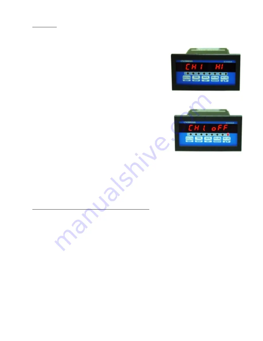
If an attempt is made to display the high or low peak of a channel which has
been turned off (in CH Setup), the display will read
'CHx OFF'
(x=channel
#) to indicate the channel status.
Peaks can be reset to the present value of process (e.g. if channel 1 is reading
200 C, its peaks can be reset to 200). This will allow tracking the process
from present temperature being read by the unit. To reset high peak, first
select the channel whose peak is desired to be reset (by pushing the
CH.
SEL
key). Once the channel has been selected, push
HI/LO
key and keep it pushed. The display will read
'HI P'
following which the value of high peak will be displayed. With
HI/LO
key still pushed, go on to push the
RESET
key.
The display will read
'RESEt'
and the unit will then take the present value of process on that channel and enter it as new
high peak. To reset low peak, release
HI/LO
key (from high peak display mode) and push it again immediately -- and
keep it pushed. The display will read
'LO P'
and then the value of channel's low peak. With
HI/LO
key still pushed,
press the
RESET
key. The display will read
'RESEt'
and the unit will enter present process value as the channel's new
low peak.
PROGRAMMING FLOW CHARTS:
FOLLOWING PAGES SHOW FLOW CHARTS FOR DPS3100 AND DPS3200 UNITS:
Summary of Contents for DPS3100 series
Page 26: ...Page 25 WARRANTY For Warranty information check Omega s web site at http www omega com...
Page 27: ...Page 26...
Page 28: ...Page 27...
Page 29: ...Page 28...


