background image


Page 9


Once the correct pass-code has been entered, the display shows 

'SYS   CH'

,  with 

'CH'

 blinking.  At this point the 

operator may choose between making channel settings (CH), or system settings (SYS).  Use 

^v

 key to toggle between CH 

and SYS modes.  When the desired mode is blinking, press 

SETUP

 key to begin setup of parameters for that mode. 

'SYS' Parameter List 


Following parameters can be setup when blinking 

'SYS'

 is selected:  


1) Display Options


3) Relay Latch/Non-latch


   a) 

Elapsed 

Time 


4) Calibration/Range setting


   b) 

SCAN   a) 

Cold 

Junction 

Reference 

Temperature 

   c) 

High 

Channel 

  b) 

Thermocouple/voltage/current 

calibration 

   d) 

Low 

Channel 

  c) 

Voltage 

Range 

   e) 

Deviation 

  d) 

Current 

Range 

   f) 

Channel 

Difference 


2) Display Time


For more details, refer to the SYSTEM CONFIGURATION section. 
 

CH Parameter List 


Following parameters can be setup when blinking 

'CH'

 is selected:  


CURRENT OR VOLTAGE INPUT


THERMOCOUPLE, RTD, THERMISTOR INPUT


1) Select Channel  


               1) Select Channel 

 2) 

Input 

Type 


2) 

Input 

type 

 3) 

Channel 

ON/OFF 


3) 

Channel 

ON/OFF 


4) Decimal Point Position   


 4) Temperature units (C or F) 

 5) 

High 

Scale 


5) 

Setpoint 


6) Low Scale 


 6) Limit 


7) Offset  


               7) Deadband 

 8) 

Tare 


8) 

Relay 

normally 

open/closed 

 9) 

Setpoint 


9) 

Engineering 

units 

           10) Limit 
           11) Deadband 
           12) Relay Normally Open/Closed 
           13) Display Units 
 
For more details, refer to the CHANNEL CONFIGURATION section. 
 
Three attempts at entering correct pass-code are allowed. 

'HELP'

 shows up in the display window if attempted pass-code 

is wrong.  If a person fails in three attempts, the system will go back to normal display mode. To make another attempt at 
this point one has to get into SETUP mode again. 
 
Three keys are used during setup --- 

SETUP

< NEXT >

, and

 ^v

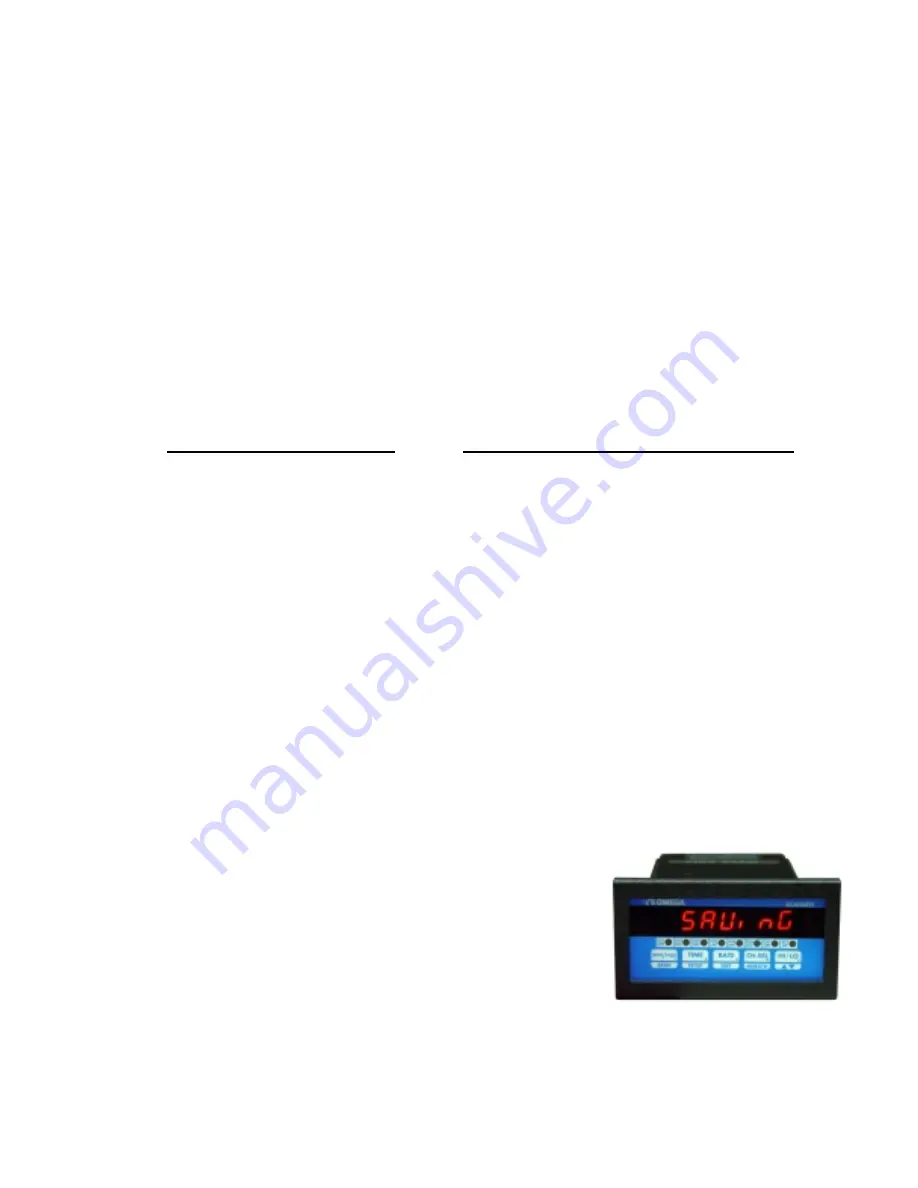
. If, at any point during SETUP, it is desired to get out of 

SETUP and back to normal display mode, push and hold the 

RESET

 key 

until the display reads 

'SAVING'

. The 

SETUP

 key takes you from one 

parameter to the next e.g. if you are setting up Channel ON/OFF,  then after 
getting the desired value push 

SETUP

 key to setup for Degrees C/F. 

<NEXT> 

and 

^v

 keys are used for programming values of parameters such 

as limits, setpoints, etc. 
 

NOTE: 

 To exit from any point during SETUP procedure or to save the 

newly made changes, simply press and hold the RESET key until the display 
shows 'SAVING'. When the display shows 'SAVING', it is indicating that the 
unchanged and the newly made changes are being saved in the EEPROM for 
permanent storage.

 It is important that the above step be performed any time  changes are made to the configuration 

of the unit and before power is removed. If not done so, all the new changes will be lost. The unit will, however, 
maintain the old settings.


Summary of Contents for DPS3100 series

Page 1: ...http www omega com e mail info omega com Omega com Omega com Omega com Omega comTM TM TM TM DPS3100 DPS3200 series Programmable Scanners...

Page 2: ...Setup For Engineering Units 13 Setup for Thermocouple Thermistor RTD Inputs 13 Turning Channels ON OFF 13 Temperature units 13 Setup Examples 13 Example 1 Use of the OFFSET Parameter 13 Example 2 Use...

Page 3: ...F INSTRUMENT 21 POWER 21 OUTPUT CONNECTOR PIN ASSIGNMENT 22 Table 1 DPS3000 Series Output Connector Pin Assignments 22 TROUBLE SHOOTING 23 Factory Channel settings 23 Factory default settings for volt...

Page 4: ...igit height Over range indication HELP Display test Briefly displays 8 8 8 8 8 8 8 on power up Seven digit display SCALE OFFSET Scale programmable from 1 30000 units Offset programmable from 0 99 99 M...

Page 5: ...up check for proper power connections before powering up the unit will first display 8 8 8 8 8 8 8 as a display test and then the software revision number The format is rEn x xx where x xx is the revi...

Page 6: ...hannel whose rate is desired push CH SEL key b Push RATE key once 4 Channel deviation a Select desired channel by pushing CH SEL key b Push RATE DIFF key twice 1st push displays rate 2nd push deviatio...

Page 7: ...ragraphs give a detailed description and operation of various modes Elapsed Time Mode DPS3000 Series can be programmed to run as timer In this mode the unit will indicate elapsed time in hours minutes...

Page 8: ...lue On push of a key the channel number and the value of process variable can be displayed Also during SYS Setup the unit can be programmed so that instead of scanning all the channels it will only di...

Page 9: ...w seconds e g CH1 CH2 for displaying difference between channel 1 and channel 2 If the unit is not programmed for difference mode the differential between any two of the seven channels can be briefly...

Page 10: ...12 Relay Normally Open Closed 13 Display Units For more details refer to the CHANNEL CONFIGURATION section Three attempts at entering correct pass code are allowed HELP shows up in the display window...

Page 11: ...will not spend any time scanning it This will also prevent the unit from displaying a HELP message on a channel that has nothing hooked up to it Use v key to select the desired setting If a channel is...

Page 12: ...the 0 130Vdc correspond to a display of 0 set OFFSET 0 130 NOTE If the input type is CURRENT the Offset value is entered in milliamps If the input type is VOLTAGE the Offset value is entered in milliv...

Page 13: ...to enter that value and go on to setup Deadband Setup For Deadband After setting a channel s LIMIT the next parameter to be set is channel s relay DEADBAND This parameter is used for eliminating rela...

Page 14: ...ke the other inputs any alternate units may be programmed for thermocouples The display will first show Cx UNIt x channel after which the current UNITS will be displayed Use v key ref Setup For High S...

Page 15: ...lay option and then the present Display Option setting Table 3 below lists all 6 display options available Use v key to step thru the options Once the desired Display Option is shown push SETUP key to...

Page 16: ...p For Cold Junction Calibration After setting Relay Latch Non Latch the next parameter is the cold junction reference temperature The display will first show COLd JN and then the cold junction tempera...

Page 17: ...e calibration for all channels Also only one type of thermocouple input needs to be calibrated i e J K T or E For example if the calibration is done for a type K thermocouple types J T and E are autom...

Page 18: ...isplay will indicate LO P for Low Peak before showing the value If an attempt is made to display the high or low peak of a channel which has been turned off in CH Setup the display will read CHx OFF x...

Page 19: ...ANGE VOLTAGE CURRENT J T C CR AL T C K T T C E T C LO VOLTAGE HI VOLTAGE CURRENT VOLTAGE CURRENT RTD 385 RTD 392 VOLTAGE CURRENT R T C S T C B T C VOLTAGE CURRENT THERMISTOR TC Option TH Option P Opti...

Page 20: ...ANGE CURRENT RANGE J T C CR AL T C K T T C E T C LO VOLTAGE VOLTAGE CURRENT RTD 385 RTD 392 R T C S T C B T C THERMISTOR TC Option TH Option MV V or C Option Not Selectable RTD Option R S or B Option...

Page 21: ...ctor outputs or electro mechanical relays Check model number printed on the unit Open Collector Option Whenever a limit is reached an open collector output provides a 5 Vdc signal at 50ma on the outpu...

Page 22: ...e made to the three terminal connector as shown in figure 3 Also make note that it is very important that the power line inputs and the power ground are not switched Doing so will permanently damage t...

Page 23: ...Channel 3 Limit Normally Open Closed Negative Output 7 Channel 4 Limit Common Positive Output 8 Channel 4Limit Normally Open Closed Negative Output 9 Channel 5 Limit Common Positive Output 10 Channel...

Page 24: ...GES AND SOLUTIONS ERROR MESSAGES AND SOLUTIONS ERROR MESSAGE ERROR CONDITION SOLUTION EE EROR The unit was unable to If the message keeps coming up save programmed value unplug the unit and reapply po...

Page 25: ...e the nuts from the mounting screws on the Panel Meter 3 Insert panel meter into the hole until it is flush with the panel 4 Install the nuts and tighten them till the unit is held firmly against the...

Page 26: ...Page 25 WARRANTY For Warranty information check Omega s web site at http www omega com...

Page 27: ...Page 26...

Page 28: ...Page 27...

Page 29: ...Page 28...

Reviews: