background image

3.

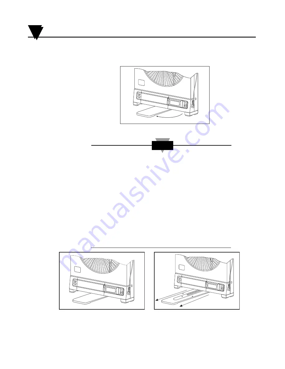
Swing out the stabilizing arm and extend it towards you.  Figure 2-2 shows
how to swing out the stabilizing arm.  Make sure the slot in the stabilizing arm
extends out the rear of the recorder.

Figure 2-2.  Swiveling Stabilizing Arm

When the recorder is in normal operating position (the door
is closed and the control panel door is closed), the stabilizing
arm should be pushed to middle position (the bumps on the
arm will click in place under the recorder).  Refer to Figure 
2-3a.

Before opening the door, pull the stabilizing arm out to its full
extension position to provide full stability.  Refer to Figure 
2-3b.  After closing the door, return the arm to its middle
position.  Refer to Figure 2-3a.

Note that the arm extends towards the front or rear of the
case.  If the unit is placed on a bench top snug against the
wall, extend the stabilizing arm fully to the front of the unit.
Refer to Figure 2-3b.

Figure 2-3a.  Stabilizing Arm use 

Figure 2-3b.  Stabilizing Arm in Extended

for Bench Top Use (normal position)

Position (position when you open door)

H

U

M

I

D

I

T

Y

RH

°

F

°

C

H

U

M

I

D

I

T

Y

RH

°

F

°

C

NOTE

Swing

H

U

M

I

D

I

T

Y

RH

°

F

°

C

Setting Up the Recorder

2

2-2

Summary of Contents for CT485B-110V-G-AL

Page 1: ...W AL High Performance Microprocessor Based Temperature and Humidity Recorder 6 7 8 9 5 4 3 RH F C 7 4 T E M P E R A T U R E H U M I D I T Y HO TO RH F C H35 T2 T E M P E R A T U R E H U M I D I T Y 7...

Page 2: ...130 621 400 FAX 33 0 130 699 120 Toll Free in France 0800 4 06342 e mail france omega com Germany Austria Daimlerstrasse 26 D 75392 Deckenpfronn Germany TEL 49 0 7059 9398 0 FAX 49 0 7056 9398 29 Toll...

Page 3: ...ial incidental or special damages CONDITIONS Equipment sold by OMEGA is not intended to be used nor shall it be used 1 as a Basic Component under 10 CFR 21 NRC used in or with any nuclear installation...

Page 4: ...able 2 11 2 6 2 Using the Remote Sensor Cable 2 12 2 6 3 Using the Sensor Clip 2 13 Chapter 3 Powering Up the Recorder 3 1 3 1 Turning on the Recorder 3 1 3 2 Recording the Code Numbers 3 1 3 3 Compar...

Page 5: ...ns 8 1 8 2 Light Bulb Display Backlighting and Push Button Information 8 2 8 3 Case Care 8 3 8 4 Storage of Chart Paper 8 3 8 5 Power Failure Mode Chart Paper Indication 8 3 Chapter 9 Troubleshooting...

Page 6: ...t Temperature and Humidity Remote Mount Sensor Digital Plots in 1 or 1 Increments Memory and Display of Peak Readings 1 7 or 32 Day Charts Battery or ac Power Operation With Automatic Battery Power Ba...

Page 7: ...adapter 3 Pen Cap Posts Holds the loose pen caps 4 Time Set Arrow Helps align the time on the new chart paper with the actual time 5 Chart Paper double sided Charts are available for 1 7 and 32 day r...

Page 8: ...g power up 2 Enters calibration codes in memory 3 Activates alarm limits 4 Enters alarm limits in memory 5 Disables the sounding of the alarm and activation of the relay for 10 seconds 11 LCD Display...

Page 9: ...ser to carry the recorder conveniently 23 Product Label Product information label 24 Alarm Relay Contacts Allows the user to hook up an external dry contact alarm to the recorder 25 Battery Compartmen...

Page 10: ...orative foot cover 1 Place the recorder on its back so it is face up 2 Remove the clip on foot cover by lifting up on the cover and releasing it from the stabilizing arm at the bottom of the recorder...

Page 11: ...a Before opening the door pull the stabilizing arm out to its full extension position to provide full stability Refer to Figure 2 3b After closing the door return the arm to its middle position Refer...

Page 12: ...er cable If the decorative foot cover is not in place go through the following steps to reinstall the cover if desired 1 Place the recorder on the table so it is front face up 2 Roughly position the f...

Page 13: ...3 1 Installing Batteries You may power the recorder with four D size batteries For adequate performance and battery life use alkaline batteries The recorder operates full time on battery power alone f...

Page 14: ...this time frame Also if the unit is operating under battery power and the battery voltage is too low to permit reliable operation the system shuts down and displays in the LCD The system may be restar...

Page 15: ...he chart type and C F switches refer to Figure 2 7 to the following positions for these six 6 modes of operation Chart Type Switch Days C F Switch Paper Type 1 F 1 day Fahrenheit paper 1 C 1 day Celsi...

Page 16: ...gure 2 9 item 1 on the spindle and rotate it until the current time on the chart paper is aligned with the time arrow on the chart base of the recorder See Figure 2 9 detail 5 When the chart paper is...

Page 17: ...he OFF or O position The front panel is located under the control panel door The recorder door should be closed too The control panel door opens easily by gently gripping the recessed area at the righ...

Page 18: ...or to insert a new pen one at a time DO NOT ATTEMPT TO OFFSET THE PENS MANUALLY BY HAND THE DRIVE MECHANISM COULD BE DAMAGED DO NOT ATTEMPT TO CHANGE THE PENS WHILE THEY ARE IN MOTION Turn off the un...

Page 19: ...ens are offset as shown in Figure 2 10 Otherwise you can damage the arm and drive mechanism if you try to remove them DO NOT ATTEMPT TO OFFSET THE PENS MANUALLY BY HAND THE DRIVE MECHANISM COULD BE DA...

Page 20: ...Cable 1 Place the handle part of the sensor in to the sensor clip on the side of the recorder as shown in Figure 2 15 Figure 2 15 Attaching the Sensor left picture Correct Position center Incorrect P...

Page 21: ...6 before mating the two cables 2 Connect the other end of the remote sensor cable without the arrow to the socket at the side of the recorder Figure 2 16 Using the Remote Sensor Cable For accurate tem...

Page 22: ...When mounting to wood or sheet rock surfaces drill two 1 16 1 5 mm diameter holes When mounting to plastic drill two 5 64 1 9 mm diameter holes Appropriate hardware must be selected when mounting to...

Page 23: ...Setting Up the Recorder 2 2 14 Notes...

Page 24: ...r display You can then compare the codes your recorder displayed with the probe label as described below After the two groups of codes are displayed the recorder continues with its sequence and the pe...

Page 25: ...lowing the letter H on the label If it does not refer to Section 5 1 Changing Calibration Codes The single character Temperature code should match the single character code following the letter T on t...

Page 26: ...8 Figure 3 8 Display Selector Switch At the same time the temperature pen and humidity pen one at a time move to the right a short distance and then move to the left to the zero position Then both pen...

Page 27: ...Powering Up the Recorder 3 3 4 Notes...

Page 28: ...on 4 2 Checking Alarm Limits WAIT UNTIL THE UNIT HAS STABILIZED AND THE PENS STOP MOVING BEFORE PRESSING ANY KEYS ON THE KEYBOARD Depending on the Display Selection Switch position the display will be...

Page 29: ...ation of the Door Lock 4 3 1 Unlocking the Control Panel Door Use a small screwdriver to turn the lock to the left as far as it will go Figure 4 3 shows the unlocked position Figure 4 3 Door Unlock Po...

Page 30: ...her the high OR low alarm limit At this time SE is displayed Figure 4 5 shows the location of the Alarm Display Buttons Figure 4 5 Alarm Display Buttons HIGH SET LOW 4 Release the SET button The displ...

Page 31: ...or the other parameters For example if you already checked or changed F you may check or change C or RH if you choose 7 After you are all done with the changes close and lock the control panel door if...

Page 32: ...rm 1 Unlock the control panel door if necessary 2 On power up when you hold the LOW button down an AO message appears in the display and the beeper sounds This will disable the alarm function This act...

Page 33: ...Alarm Operation 4 4 6 Notes...

Page 34: ...or probe and the recorder do not match A replacement probe is being used and the calibration codes must be changed to match You want the recorder to more closely match the reading of another instrumen...

Page 35: ...button to decrease the value of the character When this character is correct press the SET button 6 The second character should now be blinking Refer to Figure 5 3 If it is not press the SET button u...

Page 36: ...automatically go through the power up sequence as described in Chapter 3 If it does not hold down the SET button until it does While the unit goes through the power up sequence observe the display to...

Page 37: ...ld take to calibrate the sensor Take 33 Solution Reading after waiting one hour Take 75 Solution Reading after waiting one hour Go to Temperature Calibration Section 5 4 Too Low Too High Go to Section...

Page 38: ...s of the humidity calibration code This humidity code consists of a two digit alpha numeric code Digits may be any one of these characters 0 1 2 3 4 5 6 7 8 9 a b or c Figure 5 6 General Breakdown of...

Page 39: ...SE 2 The 33 reading is too high by n counts so INCREASE the humidity code by n counts EXAMPLE 2 you obtain a reading of 37 The error is 4 since 37 is 4 counts higher than 33 The initial humidity code...

Page 40: ...ng is too high by n counts so INCREASE the humidity code by n counts EXAMPLE 2 you obtain a reading of 76 The error is 1 since 76 is 1 count higher than 75 The initial humidity code of A5 from Case 2...

Page 41: ...the display after allowing the probe to reach equilibrium after a 15 minute warm up period 2 If the reading is TOO LOW by n counts DECREASE the temperature code code following the letter T by n count...

Page 42: ...TREME CAUTION WHEN USING THE GLUE READ THE WARNING LABEL ON THE TUBE 1 Calibrate the CT485B 2 Apply a small amount of glue to the back of the cover Refer to Figure 6 1 Figure 6 1 Glue Application DO N...

Page 43: ...Using the Cal Lock Kit 6 6 2 Notes...

Page 44: ...s used with a 10mV degree analog signal the recorder will display and record 20mV to 1200mV over the range of 2 to 120 F If the adapter is used with a 1mV degree analog signal the recorder will still...

Page 45: ...Using the Voltage Input Adapter Optional 7 7 2 Notes...

Page 46: ...igh as 120 F 49 C or as low as 32 F 0 C 121 31 73 Handle the recorder carefully DO NOT DROP IT Keep the recorder away from excessive dirt and dust Do not use the recorder or the sensor in a corrosive...

Page 47: ...serting the new bulbs in the sockets orient the bulbs to fit as shown in Figure 8 1 Figure 8 1 How to Hold the Bulb Assembly and Where the Bulbs are Located In the event that the ac power to the recor...

Page 48: ...the battery back up period and when the ac power returns It is important to have fresh D size batteries in the recorder for battery backup so you have continuous recording Figure 8 3 shows an example...

Page 49: ...8 4 Notes Maintaining the Recorder 8...

Page 50: ...itch under the control panel door is in the correct position The humidity pen blue appears to be in the wrong position Make sure the CHART TYPE 1 7 32 switch is in the correct position Make sure the m...

Page 51: ...wn Replace them with new bulbs Bulbs don t light Make sure pen caps are removed and secured on the cap posts as recommended Check that the pens are locked firmly in position in their holders Make sure...

Page 52: ...sor via an analog to digital converter The processor linearizes and temperature compensates the output of the humidity circuit employing a look up table approach The results of the processor calculati...

Page 53: ...the motor 10 4 Power Supply Supervision The recorder contains power supply monitoring and switching circuitry which enables it to be used in a variety of circumstances Under ordinary circumstances the...

Page 54: ...stive polymer Response Time 5 minutes for a 30 to 80 step change Display Resolution 1 RH Display Types 21 2 digit backlit LCD 0 5 high low battery and parameter indication Display Modes User switchabl...

Page 55: ...n Lift Automatic upon door opening pens are door mounted and lift away from the chart whenever the door opens Alarms Alarms User selectable for high or low temperature and humidity Audible Alarm Integ...

Page 56: ...20 F Input Protection up to 20Vdc or 10Vac RMS Input Impedance 330k ohms minimum Input Connections Banana jacks 0 75 spacing Cable Length 12 30 5cm Mechanical Dimensions 133 16 x 1011 16 x 25 8 H x W...

Page 57: ...Specifications 11 11 4 Notes Notes...

Page 58: ...the ferrite core information below For best radiated immunity performance when using the remote sensor cable Section 2 6 2 you will need to move the ferrite core close to the input of the recorder To...

Page 59: ...CE Approval 12 Notes 12 2...

Page 60: ...6 1 Care of Bulbs 8 2 Case 8 3 Chart Paper 8 3 Carrying Slot 1 4 Chart Paper Knob magnetic 1 2 2 7 Chart Paper Specialty Art Gallery Inside Back Cover Computer Rooms Inside Back Cover Hospitals Inside...

Page 61: ...1 Product Specifications 11 1 Push Button Light Bulb 8 2 R Relative Humidity Code 3 1 Relay Alarm Contacts 4 1 Remote Sensor Cable 6 ft 2 m 2 12 Remote Sensor Clip 2 13 Inside Back Cover Removing the...

Page 62: ...LW Lab Clean Rooms 7 days in C or F 20 to 23 9 C 68 to 75 F 40 to 55 RH CT485 LM Labs Clean Rooms 32 days in C or F 20 to 23 9 C 68 to 75 F 40 to 55 RH CT485 PW Computer Rooms Offices 7 days in C or F...

Page 63: ...rbine Paddlewheel Systems M U Totalizers Batch Controllers pH CONDUCTIVITY M U pH Electrodes Testers Accessories M U Benchtop Laboratory Meters M U Controllers Calibrators Simulators Pumps M U Industr...

Page 64: ...c Components Click to view similar products for Newport manufacturer Other Similar products are found below WTK 14 36 N TXDIN70 5TC TT J 24 72 MSS 08 5SC TT K 30 36 OTP U F OTP U M 5SC TT T 30 72 TPJ...

Reviews: